


August 1, 2008
Page 31
Heat & Glo · Tiara I B & Tiara II B · 7010-149M
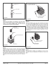
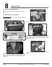
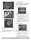
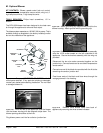
Figure 8.7 Insert inner collar adapter to rear fl ue vent.
Figure 8.8 Install vent pipe adapter with gasket or high-temp
sealant to rear vent opening. Attach with screws removed
in Figure 8.5.
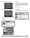
Place an appropriate grille (without a hole) gently into the
opening on top of appliance. (RV-GRILLE-T1 for the Tiara
I-B and RV-GRILLE-T2 for the Tiara II-B.)
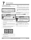
Refer to vent graph on page 12. If your installation falls
within the range of the gray shaded area of graph, it may be
necessary to make an adjustment to the vertical damper to
improve the flame appearance in your appliance.
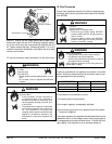
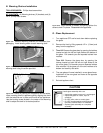
C. Damper Adjustment
1. Loosen screws using a Phillips head screwdriver.
2. Pivot the vertical damper adjustor in 1/4 in. (6mm)
increments while observing the activity.
3. Turn clockwise to open the damper = less fl ame height
and more blue in fl ame color.
4. Turn counterclockwise to close damper = increased
fl ame height and more yellow in fl ame color.
5. Make adjustment until fl ame size and activity suit your
personal preference and then retighten screws on the
adjustment control.
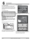
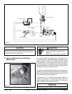
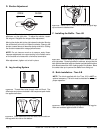
1. Top Vent Installations
OPEN
CLOSED
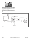
Figure 8.9 Locate the damper adjustment on the intake
plenum, accessing through the appliance front. Adjustor is
centered at the top of the appliance.
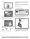
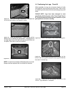
2. Rear Vent Installations
Figure 8.10
The rear vent damper is located in the back of
the firebox (behind the rear brick panel on the Tiara II-B. It is
recommended to make adjustment prior to installation.
1. Remove front/glass/ logs and brick (if installed).
2. Loosen screws and slide up to suggested settings.
3. Tighten screws
4. Reinstall front/glass/logs and brick (if applicable).
NOTE: In the Commonwealth of Massachusetts, the word
damper shall be replaced with the words flue restrictor.
Figure 8.6 Place cover plate and gasket over top vent and
attach with the eight screws removed in Figure 8.2.