


5
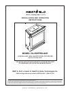
Heat & Glo • SL-550TRSI-AUE • 2079-902 Rev. B • 7/06
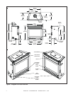
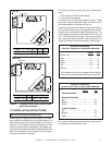
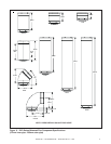
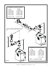
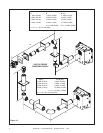
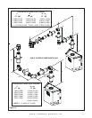
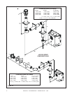
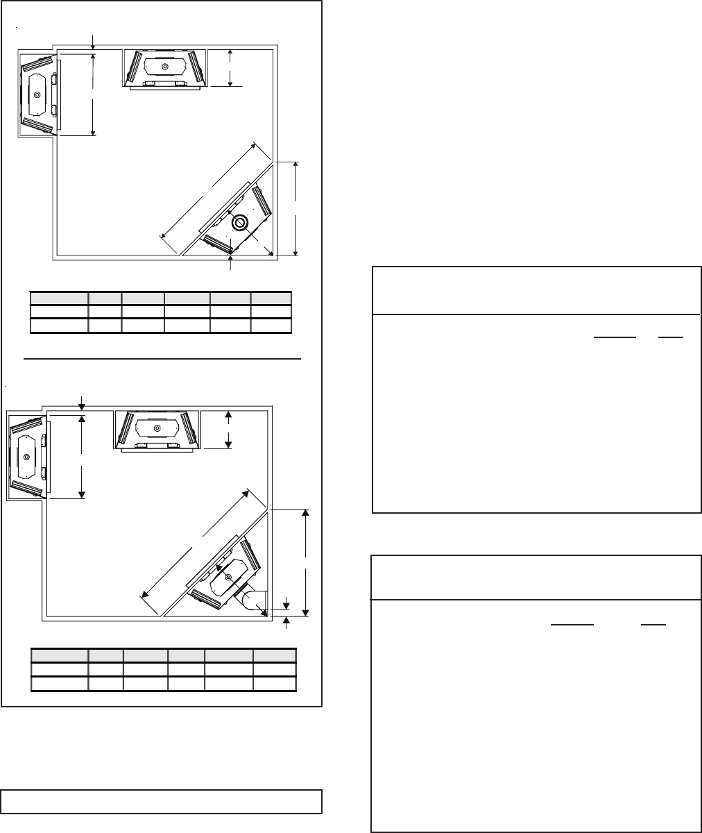
Figure 2. Fireplace Dimensions, Locations, and
Space Requirements
Minimum Clearances
from the Fireplace to Combustible Materials
Inches mm
Glass Front......................................36 ........ 914
Floor .................................................0........... 0
Rear ................................................ 1/2 ........ 13
Sides .............................................. 1/2 ........ 13
Top ................................................1 1/2 ....... 38
Ceiling* ............................................31 ........ 787
For minimum clearances, see the direct vent termina-
tion clearance in Figures 23 and 28.
Minimum Clearances
from the Vent Pipe to Combustible Materials
Inches mm
Vertical Sections. ............. 1 ................ 25
Horizontal Sections
Top ..................................... 3 ................ 75
Bottom ............................... 1 ................ 25
Sides ................................. 1 ................ 25
At Wall Firestops
Top ..................................... 3 ................ 75
Bottom ............................... 1 ................ 25
Sides ................................. 1 ................ 25
*The clearance to ceiling is measured from the top
of the unit, excluding the standoffs (see Figure 30).
1” MIN. (25mm)
B
A
E
C
1/2” MIN. (12.5mm)
D
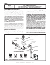
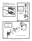
The heater can be mounted on any of the following sur-
face:
1. A flat surface (minimum 6mm base).
2. Four (4) corner supports.
(Example: Four (4) concrete masonry blocks). These
supports must be positioned so they contact all four (4)
perimeter edges on the bottom of the unit.
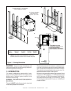
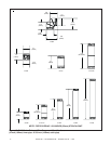
Heater framing can be built before or after the heater is
set in place. Framing should be positioned to accom-
modate wall covering and heater facing material. The
heater framing should be constructed of 2 inch X 4 inch
(51 x 102mm) lumber or heavier. The framing headers
may rest on the heater standoffs. Refer to Figure 2 and
Figure 3 for heater and framing reference dimensions.
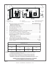
A B C D E
Inches
37 16-1/4 29-1/2 41-3/4 59
Millimeters
940 413 749 1060 1499
A B C D E
Inches 37 16-3/8 33 46-11/16 66
Millimeters 940 413 838 1186 1676
Top Flue
Rear Flue
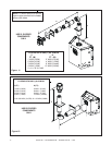
1.0 INSTALLATION INSTRUCTIONS
In planning the installation for the heater it is neces-
sary to determine where the unit is to be installed, the
type of flue system to be used (straight out, corner, or
elevated), and whether optional accessories (wall
switch or remote control) are desired. Gas supply pip-
ing should also be planned. Refer to the appliance data
plate on the base pan of the heater for all gas pres-
sures and input rate information.
NOTE: Not intended for fireplace insert.
A
1” MIN. (25mm)
B
E
C
D
3” (76mm)