


20
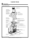
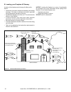
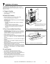
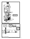
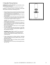
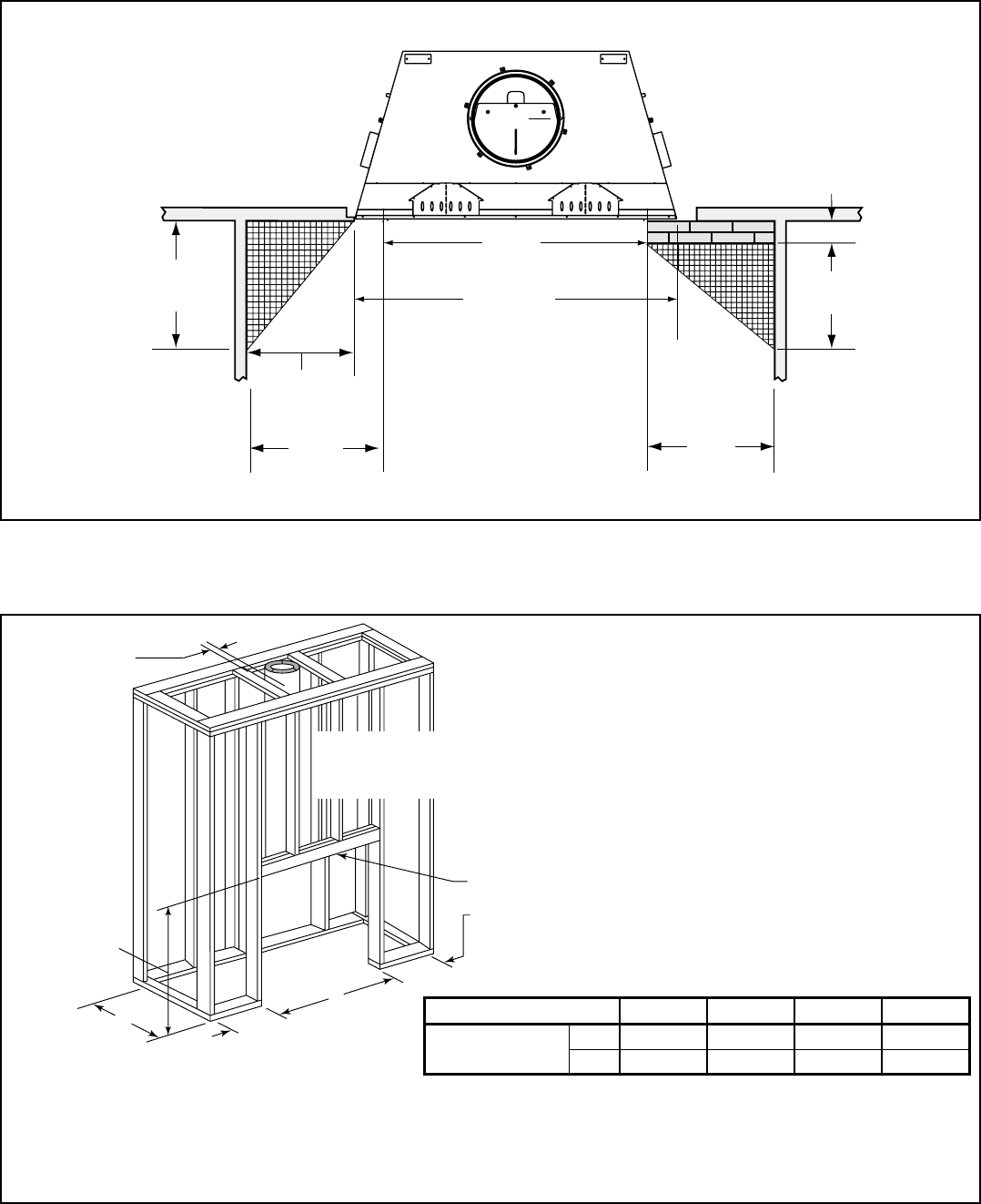
D. Frame the Fireplace
Figure 6.4 shows typical framing using combustible materials (2x4 lumber shown).
• Observe all required air space clearances to combustible materials as shown in Figure 6.2.
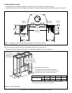
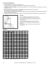
18 1/2 in.
[470 mm]
19 3/4 in.
[500 mm]
4 in.
[102 mm]
50° angle
39° angle
24 in.
[610 mm]
BRICK
FRONT
FLUSH
FRONT
24 in.
[610 mm]
22 3/8 in.
[568 mm]
52-7/8 in.
(1343 mm)
42 in.
[1067 mm]
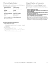
Note: Grid depicts 1 inch squares.
Figure 6.3 Mantel Leg, Surround or Wall Projection (acceptable on both sides of opening)
B
C
A
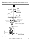
2 in. (51 mm)
min. air space
clearance
from chimney.
Note: Framing must be
extended straight up,
all the way to the ceiling.
Header MUST NOT be notched!
D
D = extra space needed for outside air connection.
If outside air duct has no bend, this dimension may be
reduced as long as minimum clearances are met.
D
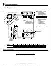
Figure 6.4 Framing the Fireplace
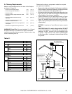
C. Sidewalls/Surrounds
• Locate adjacent combustible sidewalls a minimum of 24 in. (610 mm) from fi replace opening.
• Mantle leg, surround, stub wall, whether combustible or noncombustible, may be constructed as shown in Figure 6.3.
Model # A B * C ** D
RUTHERFORD-42 in. 53 7/8 28 3/8 74 1/2 12
mm 1368 721 1892 305
* If interior of chase will be drywalled, add the thickness to this meaurement.
** Adjust header height for raised fl oor under fi replace.
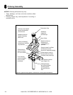
Heat & Glo • RUTHERFORD-42 • 4059-309 Rev G • 11/08