


Heat & Glo LifeStyle Collection • Twilight-II-B • 2108-900 Rev. G • 8/07 19
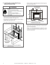
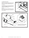
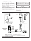
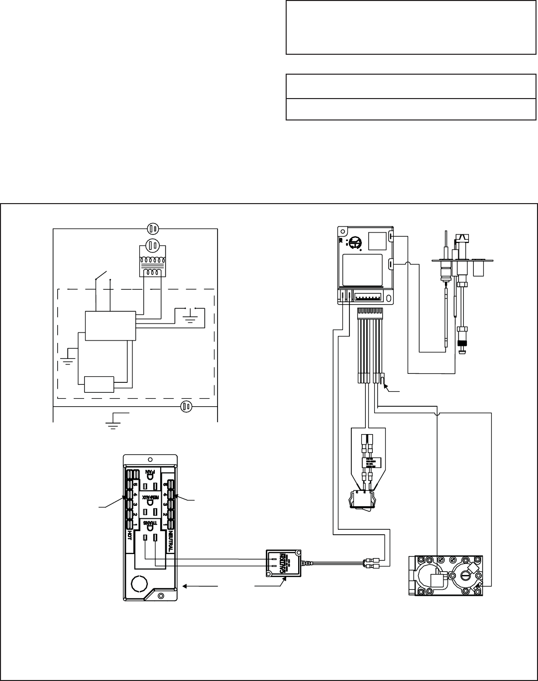
Figure 7.3 Intellifi re Pilot Ignition (IPI) Wiring Diagram
*
NOTE: 1. Ignition module, valve, pilot, and wall switch operate on 3 volts.
Uninterrupted 120 VAC is required at junction box unless equipped with battery back-up.
D. Intellifi re Ignition System Wiring
This appliance requires a 110 VAC supply to the appliance
junction box for operation. When using the transformer,
the junction box must have uninterrupted 120V. A wiring
diagram is shown in Figure 7.3.
This appliance is equipped with an Intellifi re control valve
which operates on a 3 volt system.
This appliance is supplied with a battery pack and a 3 volt AC
transformer, which requires the installation of the supplied
junction box. It is highly recommended that the junction box
be installed at this time to avoid reconstruction.
The battery pack requires two D cell batteries (not included).
CAUTION
Battery polarity must be correct or module damage will occur.
Optional Accessories Requirements
Wiring for optional accessories should be done now to
avoid reconstruction.
IGNITION MODULE
3 VAC
TRANSFORMER
3 VAC
GRN
ORG
INTERMITTENT
PILOT
IGNITOR
IGNITION
MODULE
(3V)
ON/OFF
WALL
SWITCH
LOW VOLTAGE
PLUG-IN
3V TRANSFORMER
NEUTRAL
HOT
GROUND
FLAME SPARKER/
SENSOR
REMOTE
CONTROL
SEE NOTE 1
ORG
WHT
VALVE
PIGGYBACK
ON/OFFSWITCH
WHITE WIRE
CAN BE
PLUGGED
INTO ANY
OF #1-#5
LOCATIONS
ON THE
NEUTRAL SIDE
BLACK WIRE CAN BE
PLUGGED INTO ANY OF
#1 - #5 LOCATIONS
ON THE HOT SIDE
BRN
BRN
VALVE
PLUG IN
GROUND TO
FIREPLACE
CHASSIS
I
S
NOTE: Batteries cannot be placed in the battery pack while
using the 3 volt AC transformer. The transformer must be
unplugged if the battery pack is used or battery life will be
reduced.