


Hearth & Home Technologies • GFK4B Fan Kit • 4016-095 Rev H • 11/08
3
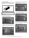
3. Install the Fan
Position the fan all the way to the rear and center in the
appliance. Press the fan (magnets to the bottom) to the
back of the appliance. See Figure 7. Plug the fan cord
into the fan receptacle labeled “FAN” on the junction box.
See Figure 8.
BOTTOM PAN
APPLIANCE
BACK
FAN
FIREBOX
BOTTOM
Figure 7 Rotate Fan
Junction Box
Fan Assembly
Cord
Clips
Figure 8 Position the Fan
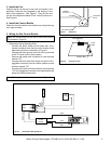
5. Wiring the Fan Control Module
Wall
Switch
RS
Valve
TP
TH
TH
TP
Fan
Control
Module
Black/White
Black Ground
Black
Red
White
Thermopile
Red
White
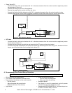
Figure 9 Robertshaw Wiring Diagram
4. Install the Control Module
Attach the control module to the bottom pan using the mag-
netic tape provided.
Note: Fan control timer only for use on units with junction
box pictured in Figure 9.
• Robertshaw Valve (Standing Pilot)
- Connect the black, white and red wires with 1/4 in.
female connectors from the fan control module to the
appliance junction box as shown in Figure 9.
- Connect the black ground wire with the ring terminal
to the TP screw on the valve (center).
- Remove wall switch wire connected to valve terminal
marked “TH”.
- Connect the black with white stripe wire with 3/16 in.
piggyback connector from fan control module to valve
terminal marked “TH”.
- Connect wall switch wire removed from valve terminal
“TH” to the piggyback connector on the black with white
stripe fan control module wire.
Note: Thermopile must be wired as shown in Figure 9.