


31
Heatilator • GBST4336I, GBFL4136I • 2135-900 Rev. D • 11/08
RED
VALVE
TRANSFORMER 3V
BLACK
BROWN
GROUND TO
FIREPLACE CHASSIS
TEMP SENSOR
BATTERY PACK
ORG
GREEN
BROWN
PLUG-IN
BLACK
BLACK
REMOTE RECEIVER
PLUG IN
WHITE
ORANGE
IGNITION
MODULE 3 VAC
INTERMITTENT
PILOT IGNITOR
I
S
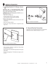
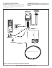
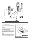
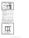
Figure 12.2 Intellifi re Ignition Wiring Diagram with Remote Receiver
ROMEX CONNECTORS
Figure 12.3 Junction Box Detail
NOTICE: DO NOT wire
110 VAC to wall switch.
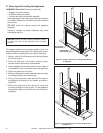
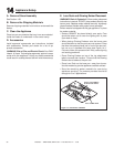
E. Junction Box Installation
The junction box must be wired from the INSIDE of the
appliance:
• Determine which side of the appliance the junction box
is located on.
• Pull the electrical wires from outside the appliance through
the knockout making sure to use a Romex connector to
fasten the electrical wires to the unit.
• Pull enough wire into the valve compartment to easily reach
the junction box location.
• Remove the screw attaching the junction box to the junction
box bracket and set it aside.
• Route the wire through the knockout in the junction box
bracket.
• Wire the junction box and reattach it to the bracket by
inserting the tab in the slot and attaching with screw
previously removed. Ensure that a Romex connector is
used to attach the electrical wires to the junction box.