


Heatilator • GBST4336I, GBFL4136I • 2135-900 Rev. D • 11/08
26
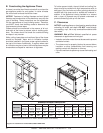
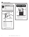
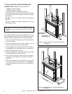
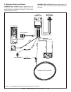
NAILING TABS
(BOTH SIDES)
PILOT HOLES
(BOTH SIDES)
C. Securing and Leveling the Appliance
WARNING! Risk of Fire! Prevent contact with:
• Sagging or loose insulation
• Insulation backing or plastic
• Framing and other combustible materials
Block openings into the chase to prevent entry of blown-
in insulation. Make sure insulation and other materials
are secured.
DO NOT notch the framing around the appliance
standoffs.
Failure to maintain air space clearance may cause
overheating and fi re.
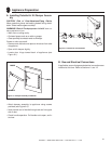
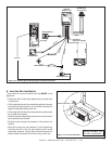
The diagram shows how to properly position, level, and
secure the appliance (see Figure 9.3). Nailing tabs are pro-
vided to secure the appliance to the framing members.
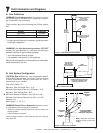
1. Venting - refer to Vent Clearances and Framing (Section
8) for hole location.
2. Place the appliance into position, making sure to
maintain proper clearance to combustibles.
3. Level the appliance from side to side and front to back. It
is acceptable to use wood shims under the appliance.
4. Fasten the appliance to the fl oor.
5. Bend out nailing tabs on each side making sure to keep
the nailing tabs fl ush with the framing.
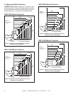
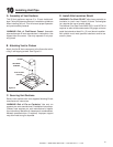
6. Using a framing square, make sure that the sides of
the appliance are square to the bottom as shown in
Figure 9.4.
7. Secure the appliance to the framing by using nails
or screws through the nailing tabs. It is acceptable to
use plumber strap to secure the unit to the framing if
necessary.
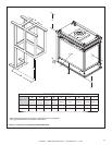
Figure 9.3 Proper Positioning, Leveling And Securing of
an Appliance
SIDE TO SIDE
FRONT TO BACK
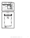
90°
Figure 9.4 Proper Positioning, Leveling And Securing of
an Appliance
NOTICE: Failure to ensure that the fi replace opening
is square may result in the decorative front not fi tting
properly.