


20
60 5/8 in.
[1540 mm]
50 in.
[1270 mm]
24 in.
[610 mm]
19 3/4 in.
[502 mm]
24 in.
[610 mm]
22 3/8 in.
[568 mm]
FLUSH
FRONT
4 in.
[102 mm]
BRICK
FRONT
50° angle
39° angle
Grid represents
inch scale.
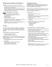
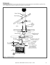
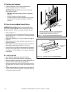
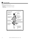
D. Frame the Fireplace
Figure 6.4 shows typical framing using combustible materials (2x4 lumber shown).
• Observe all required air space clearances to combustible materials as shown in Figure 6.1 & 6.2.
• Framing across the top of fi replace must be above top standoffs.
Note: Fireplace header
cannot be positioned until
after the fireplace
assembly is in place.
Use only noncombustible
material below the top of
the front standoffs.
2 in. (51 mm)
minimum air
space clearance
to the enclosure.
30 1/2 in.*
(772 mm)
61 5/8 in.
(1565 mm)
8 in. (203 mm) extra space
needed (both sides) for outside air
connection. If outside air duct has
no bend, this dimension may be
reduced as long as minimum
clearances are met.
Figure 6.4 Framing the Fireplace
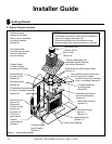
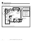
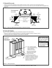
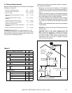
C. Sidewalls/Surrounds
• Adjacent combustible sidewalls must be located a minimum of 24 in. (610 mm) from the fi replace opening.
• Combustible and noncombustible mantel legs, surrounds and stub walls may be constructed within the gridded area,
Figure 6.3.
Figure 6.3 Mantel Leg or Wall Projections (Acceptable on both sides of opening)
* If interior of chase
will be drywalled, add
the thickness to this
measurement.
Note: Fireplace header
cannot be positioned
until after the fireplace
assembly is in place.
Heat & Glo • EXCLAIM-50 • 4013-041 • Rev U • 11/08