


Heat & Glo • EM-415/EM-415H • 31317 Rev Q • 10/06
18
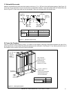
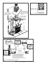
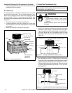
B. Using Offsets/Returns
To bypass any overhead obstructions, the chimney may be
offset using an offset/return.
An offset and return may be attached together or a chimney
section(s) may be used between an offset and return.
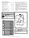
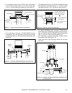
Perform the following steps to determine the correct chim-
ney component combination for your particular installation:
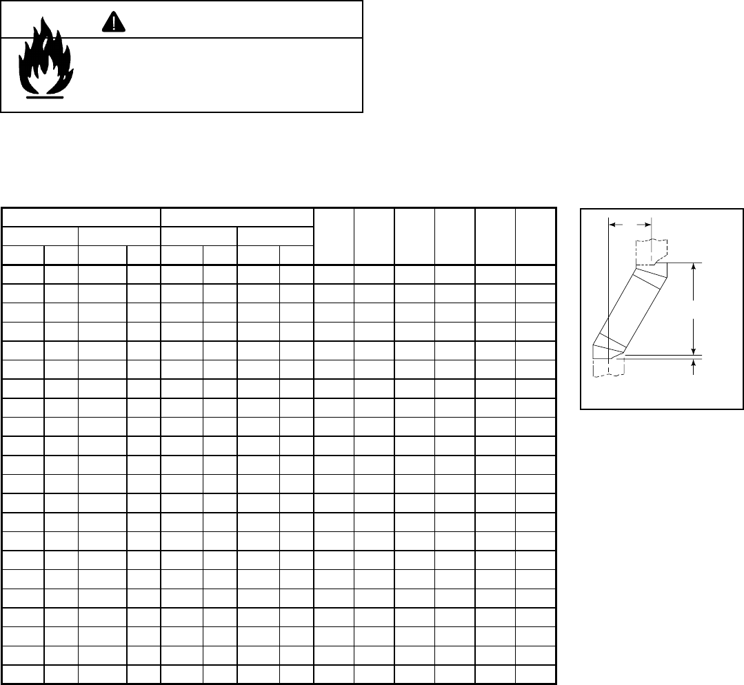
• Measure how far the chimney needs to be shifted to enable
it to avoid the overhead obstacle. See Figure 5.3. Use
dimension “A” to determine chimney section required to
achieve the needed shift.
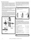
• After determining the offset dimension, refer to Table 5.2
and fi nd the “A” dimension closest to but not less than the
distance of shift needed for your installation.
• The “B” dimension that coincides with the “A” dimension
represents the required vertical clearance that is needed
to complete the offset and return.
• Read across the chart and fi nd the number of chimney
sections required and the model number of those particular
chimney parts.
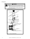
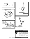
• Whenever the chimney penetrates a fl oor/ceiling, a ceiling
fi restop must be installed.
• The effective height of the fi replace assembly is measured
from the base of the fi replace to the top of the starter collar.
See Dimensions in Section 12.
Table 5.2
Fire Risk
• Draft will be restricted if offset/returns
greater than 30° are used.
WARNING
15-degree 30-degree
SL306 SL312 SL318 SL324 SL336 SL348
ABAB
in. mm in. mm in. mm in. mm
1-5/8 41 13-3/8 340 3-5/8 92 15-1/2 394 ------
2-7/8 73 17-3/4 451 5-1/2 140 18-5/8 473 1 -----
4-1/8 102 22-3/8 568 7-1/4 184 21-3/4 552 2 -----
4-1/2 114 23-5/8 600 8-1/2 216 23-3/4 603 - 1 - - - -
5-3/4 146 28-1/4 718 10-1/4 260 27 686 1 1 - - - -
6 152 29-3/8 746 11-1/2 292 29 737 - - 1 - - -
7-1/4 184 34 864 13-1/4 337 32-1/8 816 - 2 - - - -
7-3/4 197 36-1/8 918 14-1/2 368 34-1/8 867 - - - 1 - -
8-3/4 222 39-3/4 1010 16-1/4 413 37-3/8 949 1 - - 1 - -
10-3/8 264 45-5/8 1159 19-1/4 489 42-1/2 1080 - - 2 - - -
10-5/8 270 46-3/4 1187 20-1/2 521 44-5/8 1133 ----1-
11-7/8 302 51-3/8 1305 22-1/4 565 47-3/4 1213 1 - - - 1 -
13-1/2 243 57-1/4 1454 25-1/4 641 52-7/8 1343 - - - 2 - -
13-3/4 349 58-3/8 1483 26-1/2 673 55 1397 -----1
15 381 63 1600 28-1/4 718 58-1/8 1476 1 ----1
16-1/2 419 68-3/4 1746 31-1/4 794 63-1/4 1607 - 1 - - - 1
18 457 74-5/8 1895 34-1/4 870 68-1/2 1740 - - 1 - - 1
19-5/8 498 80-3/8 2042 37-1/4 946 73-3/4 1873 - - - 1 - 1
20-5/8 524 84-1/8 2137 39-1/8 994 76-7/8 1953 1 - - 1 - 1
22-3/4 578 91-7/8 2334 43-1/4 1099 84-1/8 2137 ----11
24 610 96-1/2 2451 45-1/8 1146 87-1/4 2216 1 - - - 1 1
25-7/8 657 103-1/2 2629 49-1/4 1251 94-1/2 2400 -----2
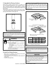
Proper assembly of air-cooled chimney parts result in an overlap at chimney joints of 1-1/4 in. (32 mm). Effective
length is built into this chart.
A
B
1-1/4 in. (32 mm)
OVERLAP
Figure 5.3 Chimney Offset/
Return
Example: Your “A” dimen-
sion from Figure 5.3 is
14 1/2 in. (368 mm). Using
Table 5.2 the dimension
closest to, but not less
than 14 1/2 in. (368 mm)
is 14 1/2 in. (368 mm)
using a 30° offset/return.
It is then determined from
the table that you would
need 34 1/8 in. (867 mm)
(Dimension “B”) between
the offset and return. The
chimney component that
best fi ts your application is
one SL324.