


Heatilator • Caliber Mesh CD Series-SIT Valve • 4040-849 Rev J • 06/0850
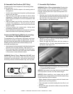
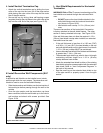
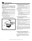
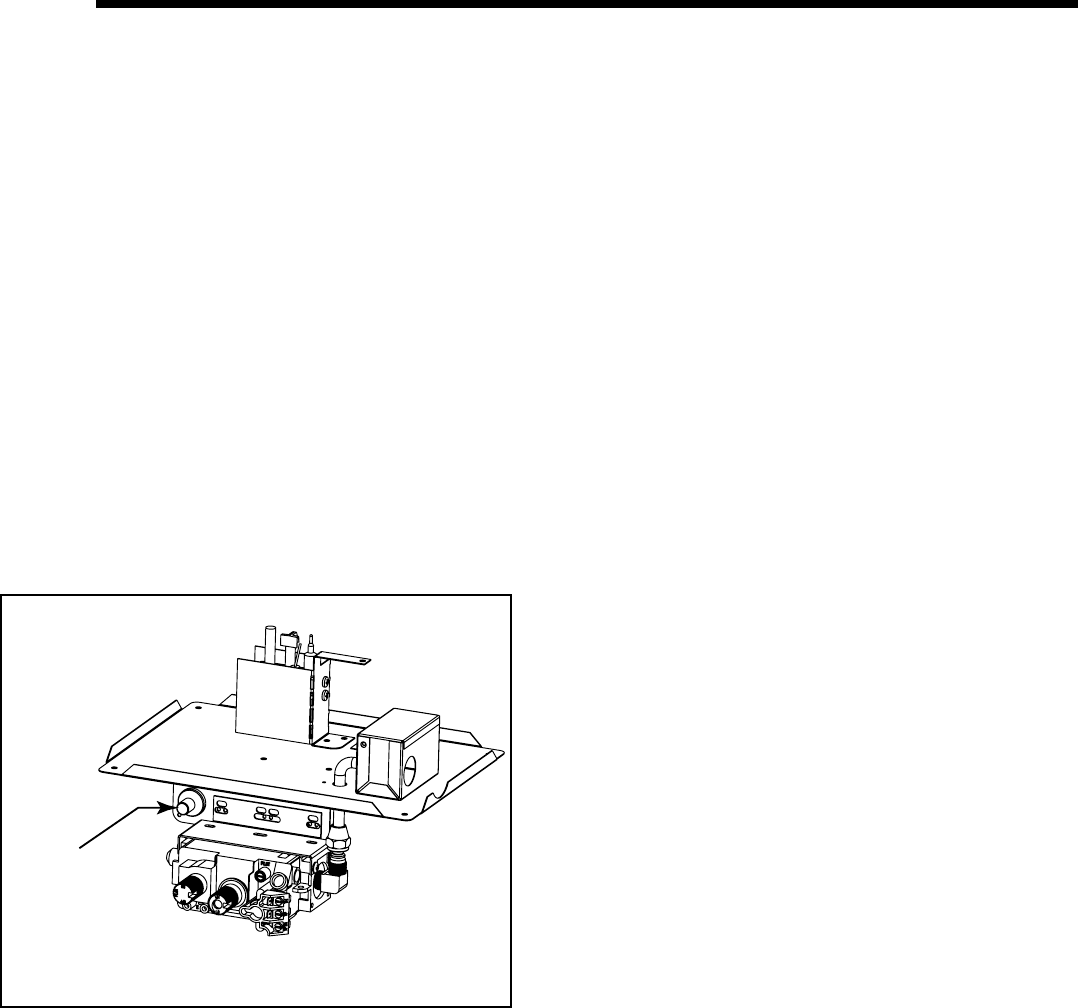
Ignitor Button
Figure 12.1 Ignitor Button
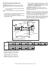
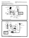
B. Standing Pilot Ignition System Wiring
• The standing pilot ignition system wiring does not require
a 110 VAC supply to operate.
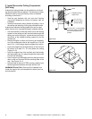
• A 110 VAC junction box MUST be installed for use with
a fan or remote control. See Figure 12.2 for junction box
wiring. Keep wire lengths short as possible.
NOTICE: DO NOT wire 110 VAC to the millivolt valve! This
will damage the valve.
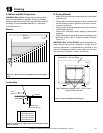
• If using a thermostat use one compatible with a millivolt
gas valve system:
- Install the thermostat in the location as indicated
in the thermostat instructions to ensure proper
operation of appliance.
- Use low resistance thermostat wire for wiring from
ignition system to the wall switch and thermostat.
- Keep wire lengths short as possible.
A. Wiring Requirements
NOTICE: This appliance must be electrically wired
and grounded in accordance with local codes or, in the
absence of local codes, with National Electric Code
ANSI/NFPA 70-latest edition or the Canadian Electric
Code CSA C22.1.
• Wire the appliance junction box to 110-120 VAC. This is
required for use of optional accessories (standing pilot
ignition) or proper operation of the appliance (Intellifi re
ignition).
• Low voltage and 110 VAC voltage cannot be shared
within the same wall box.
WARNING! Risk of Shock or Explosion! DO NOT wire
110V to the valve or to the appliance wall switch. Incorrect
wiring will damage controls.
Determine if the appliance uses an Intellifi re ignition sys-
tem or standing pilot ignition system:
• Open the control access panel.
• A red or black ignitor button (as shown in Figure 12.1)
indicates this appliance is standing pilot ignition.
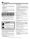
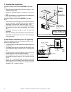
C. Intellifi re Ignition System Wiring
• Wire the appliance junction box to 110 VAC for proper
operation of the appliance.
WARNING! Risk of Shock or Explosion! DO NOT wire
IPI controlled appliance junction box to a switched circuit.
Incorrect wiring will override IPI safety lockout.
• Refer to Figure 12.3, Intellifi re Pilot Ignition (IPI) Wiring
Diagram.
• This appliance is equipped with an Intellifi re control valve
which operates on a 3 volt system.
• Plug the 3-volt AC transformer into the appliance junction
box to supply power to the unit OR install two D cell
batteries (not included) into the battery pack before
use.
NOTICE: Batteries should not be placed in the battery
pack while using the transformer. Remove batteries before
using the transformer, and unplug the transformer before
installing the batteries. Battery polarity must be correct or
module damage will occur.
D. Optional Accessories Requirements
• This appliance may be used with a fan, wall switch, wall
mounted thermostat and/or a remote control.
12
12
Electrical Information
Wiring for optional Hearth & Home Technologies ap-
proved accessories should be done now to avoid re-
construction. Follow instructions that come with those
accessories.