


Page 18
250-6422E
September 1, 2008
R
Castile Pellet Stove
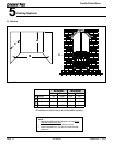
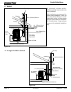
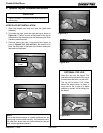
3 to 3 inch Top Vent Adapter
3 to 6 inch Top Vent Offset Adapter
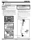
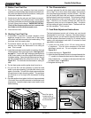
1. Put a layer of high temperature silicone on the 3 inch
(76mm) rearexhaust outlet. Figure 18.4
2. Slide the top vent adapter onto the rear exhaust outlet
and adjust the assembly to a vertical position. Figure
18.4
3. Drill 4 holes with #26 drill bit (provided) into the back
of the appliance using the outer shield as a pattern
(make sure the assembly is vertical). Figure 18.4
4. Install the 4 mounting screws.
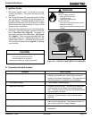
5. Drill 2 holes with #26 drill bit through the rear exhaust
outlet using the 2 holes already in the short horizontal
pipe in the top vent adapter as a guide. Install the 4
screws. Figure 18.5.
6. Install the vent pipe into the top vent adapter (be sure
to silicone all joints).
C. Top Vent Adapter Installation
Figure 18.5
Figure 18.4
Installing the Top Vent Adapter
Top Vent Adapter
3 to 3 inch
Rear Exhaust Outlet
Use hole on each side
as drilling guide
Offset Collar
3 to 6 inch
Mount with
4 screws
Clean-Out Cover
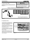
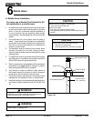
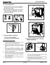
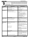
B. Leg Leveling System
Figure 18.3 - Bolt fully extended
Figure 18.2
Figure 18.1
1. Thread Allen bolts through nuts until flush. Figure 18.1.
The
Allen bolts and nuts are included in the component
pack inside the stove firebox.
2. Slide assembled nuts and bolts into slots on legs with
the nuts on the bottom. Figure 18.2. Use a 5/32 in.
(3.96mm) Allen wrench to adjust legs up and down to
desired level. Figure 18.3
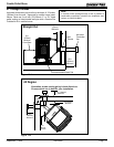
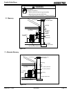
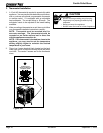
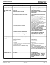
D. Rear Vent and Rear Vent to Top Vent
Adapter Installation
Clean-Out Cover
Clean-Out Cover
Figure 18.6
Figure 18.7
1. Put a layer of high temperature silicone on the 3 inch
(76mm) exhaust outlet. Figure 18.4
2. Slide the adapter onto the rear exhaust outlet and adjust
the assembly to the appropriate position.
3. Install the vent pipe into the adapter (be sure to silicone
all joints)
Rear Vent
Rear to Top Vent