


Hearth & Home Technologies • Bravo, Aztec • InD • 703-900 Rev. N • 8/06
12
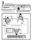
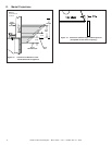
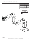
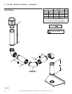
Figure 5.3
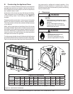
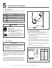
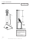
Figure 5.4
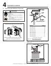
D. Vent Diagrams
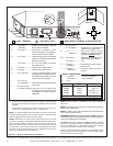
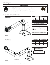
WARNING
1. Top Vent - Horizontal Termination
One Elbow
Two Elbows
NOTE: When venting with one elbow, a
straight section of venting (3 ft. minimum)
MUST be attached directly to starting col-
lars on unit.
NOTE:
V
1
MUST be a
minimum of 3 feet.
V
1
Minimum H
1
Maximum
3 ft. 0.9 m 2 ft. 0.6 m
4 ft. 1.2 m 4 ft. 1.2 m
5 ft. 1.5 m 6 ft. 1.8 m
12 ft. 3.7m 20 ft. 6.1 m
V
1
+ H
1
= 40 ft. (12.2 m) Maximum
H
1
= 20 ft. (6.1 m) Maximum
NOTE: The fi rst elbow used MUST always
be DVP90ST.
Fire Risk. Explosion Risk.
Do NOT pack insulation or other combustibles between ceiling fi restops.
• ALWAYS maintain specifi ed clearances around venting and fi restop systems.
• Install wall shield and ceiling fi restops as specifi ed.
Failure to keep insulation or other material away from vent pipe may cause fi re.
NOTE: The first elbow used
MUST always be DVP90ST.
V
1
Minimum H
1
+ H
2
Maximum
3 ft. 0.9 m 2 ft. 0.6 m
4 ft. 1.2 m 4 ft. 1.2 m
5 ft. 1.5 m 6 ft. 1.8 m
12 ft. 3.7 m 20 ft. 6.1 m
V
1
+ H
1
+ H
2
= 40 ft. (12.2 m) Maximum
H
1
+ H
2
= 20 ft. (6.1 m) Maximum
Í
Í