


Hearth & Home Technologies • BE-36-C, BE-36-CIPI • 397-981 Rev. R • 2/05
23
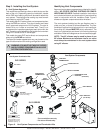
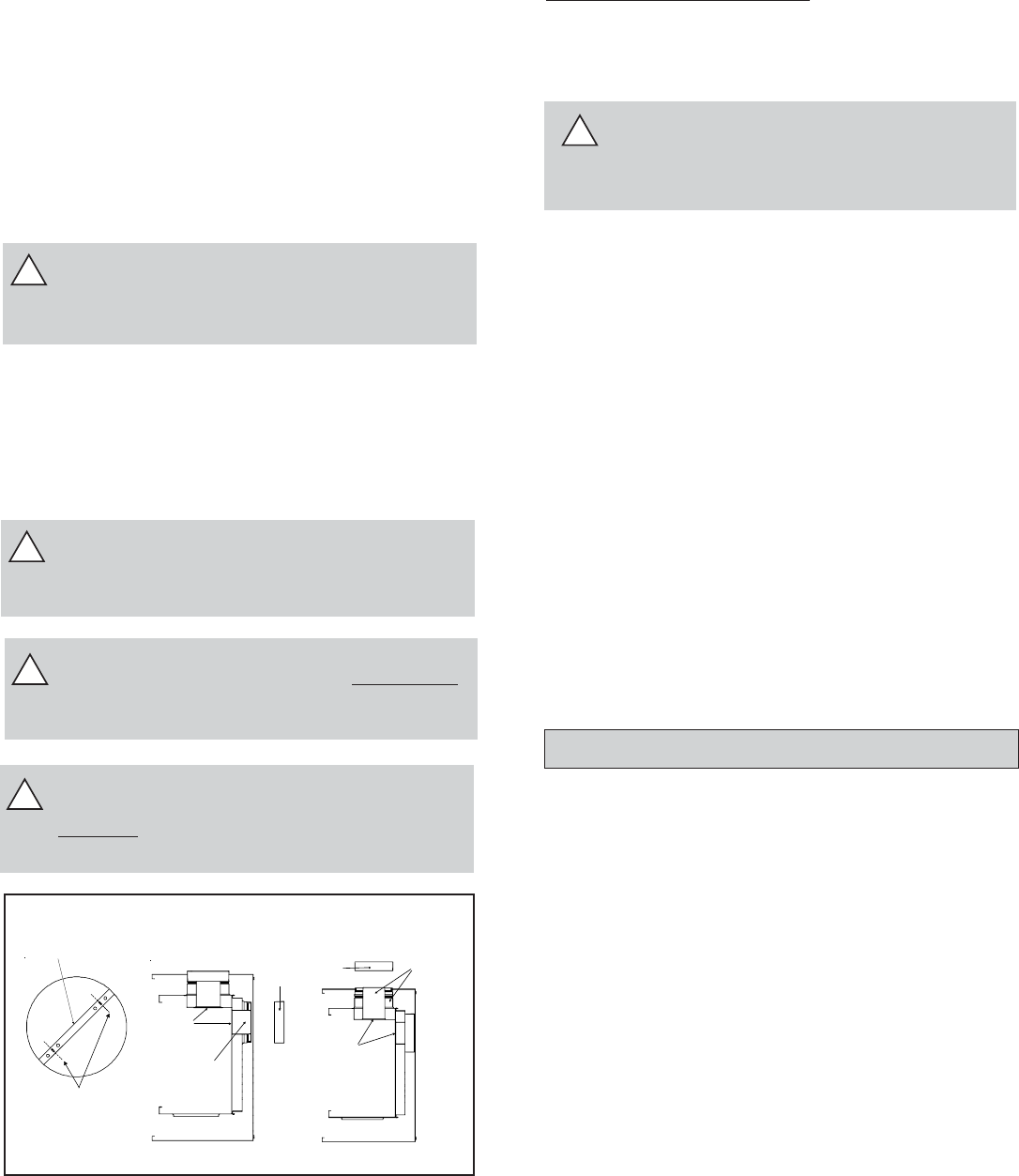
B. Installing Vent Components
After determining which set of starting collars will be used
(top or rear), follow venting instructions accordingly.
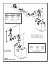
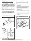
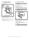
Venting Out the Rear Vent (See Figure 17)
Remove the installed rear seal cap from the rear starting
collars by cutting the strap at each end. Remove the
insulation inside the 5” collar. Follow the vent configuration
tables accordingly.
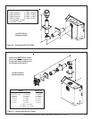
Remove the 5” diameter heat shield from the 5” diameter
collar by sliding it out.
WARNING: THE TOP HEAT SHIELD (INSIDE
THE FIREBOX) MUST REMAIN ATTACHED IF
THE VENT SYSTEM IS ATTACHED TO THE
REAR STARTING COLLARS. SEE FIGURE 17.
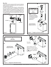
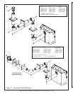
Venting Out the Top Vent
Remove the top vent collar seal cap by cutting the strap at
each end. Remove the insulation inside BOTH the 4”
diameter and 6 5/8” diameter collars. (See Figure 17).
Remove the 4” diameter heat shield from the 4” diameter
collar by sliding it out.
!
Figure 17.
Insert screwdriver
or similar object
here to remove cap.
CUT HERE
Venting
Out Rear
Venting
Out Top
!
WARNING: THE REAR VENT COLLAR SEAL
CAP MUST REMAIN ATTACHED TO THE REAR
VENT COLLARS IF THE VENT SYSTEM IS ATTACHED
TO THE TOP STARTING COLLARS. SEE FIGURE 17.
HEAT
SHIELD
DISCARD
INSULATION
SEAL
CAP
SEAL
CAP
HEAT
SHIELD
INSULATION,
DISCARD
BOTH
PIECES
!
WARNING: FAILURE TO REMOVE INSULATION
IN THE SET OF COLLARS YOU ARE USING
COULD NEGATIVELY AFFECT FIREPLACE
PERFORMANCE.
!
WARNING: YOU MUST LEAVE THE INSULA-
TION IN PLACE IN THE SET OF COLLARS YOU
ARE NOT USING. FAILURE TO DO THIS COULD
CAUSE A FIRE.
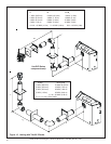
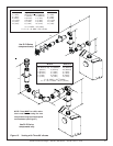
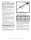
DVP Series Venting Only:
1. Attaching the Venting to the Fireplace
Refer to Cinch Pipe and Termination Cap installation in-
structions.
!
WARNING: ENSURE THAT THE FIBERGLASS
GASKET SUPPLIED WITH THE FIREPLACE SEALS
BETWEEN THE FIRST VENT COMPONENT AND
THE OUTER FIREPLACE WRAP.
If the installation is for a termination cap attached directly
to the fireplace, skip to the sections, Install Firestops and
Vent Termination.
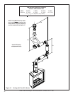
2. Continue Adding Vent Components
Refer to Cinch Pipe and Termination Cap installation in-
structions.
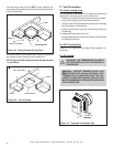
• Continue adding vent components, locking each succeed-
ing component into place.
• Ensure that each succeeding vent component is secure-
ly fitted and locked into the preceding component in the
vent system.
• 90° elbows may be installed and rotated to any point
around the preceding component’s vertical axis. If an el-
bow does not end up in a locked position with the pre-
ceding component, attach with a minimum of two (2)
sheet metal screws.
3. Install Support Brackets
Refer to Cinch Pipe and Termination Cap installation in-
structions.
Go to Step 4 Install Firestops.