


Heat & Glo • 6000GCF-IPI, 6000GCF-IPILP • 2110-900 Rev. H • 11/08 49
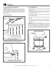
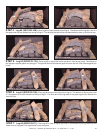
Figure 14.19 Top View
Figure 14.13 Top View
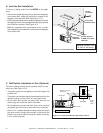
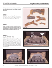
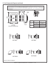
STEP 5. Log #3 (SRV2103-110): Place log #3 on top of the burner surface in front of the hump. The bottom of
the log has a square groove cut through it. The groove sits over the second grate tine from the left. Slide it back against the
hump.
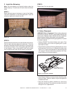
STEP 4. Log #2 (SRV2103-108): Place log #2 on top of the left side of log #1. The bottom of this log has a slot in it
that goes over the tab molded into the top of log #1. The left end sits behind the simulated ember cluster on the burner top.
STEP 6. Log #4 (SRV2103-109): Place log #4 on top of the right side of log #1. The bottom of this log has a slot
in it that goes over the tab molded into the top of log #1. The other end of the log rests on the grate, against the second tine
from the right.
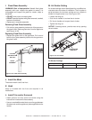
STEP 7. Log #5 (SRV2103-111): Place log #5 in front of log #3 the notch in the bottom of this log rests over the
center tine on the grate. The log shouldn’t cover any ports.
Figure 14.15 Top View
Figure 14.17 Top View
2
2
3
3
4
4
5
5
3
3
5
5
4
4
Figure 14.12 Front View
Figure 14.14 Front View
Figure 14.16 Front View
Figure 14.18 Front View
2
2