


3100-I ACT WOOD INSERT
Page 14 September 1, 2008
R
250-6381D
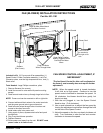
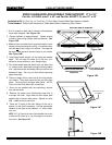
ZERO CLEARANCE ADJUSTABLE TRIM SUPPORT, 2” to 10”
Part No. 841-0990, size 9” x 45” and Part No. ADJSPT-12, size 12” x 50”
Included in Kit: (1) Trim Top, (1) Trim Front, (2) Trim Sides, Double-Sided Tape (already installed)
Tools Needed: Phillips Head Screwdriver, Sheet Metal Shears, Measuring Tape, Gloves
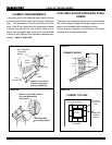
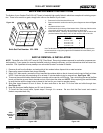
1. The 10 screws on each set of scissors will already be
loose when shipped. See Figure 14A.
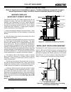
2. Expand scissors to desired height. Tighten screws
to hold in place using Phillips Head screwdriver. See
Figure 14B.
3. Measure front and side trims to required height to cover
scissors and mark pieces for cutting. Cut excess mate-
rial from top of trim’s edge, not bottom. This edge will
be sharp; wear gloves to prevent injury to your hands.
See Figure 14B.
4. Using sheet metal shears, cut trim along the marked
edge. The cut edge ts under lip of top trim, so it
allows for some variance in your straight edge.
5. The double-sided tape that holds front and side trims
to scissors has a particularly powerful bonding adhe-
sive. Adjustments are extremely difcult once trim has
adhered to tape. Do a dry run rst without removing
paper from tape.
6. Place cut edge of trim under top lip and into position
on scissors. Place side pieces on rst and then front
piece. The front piece overlaps side pieces. NOTE:
The trim in the Flush Mount Kit is one piece.
7. Once you are satised with the positioning, remove
trim and set aside.
8. Remove the paper from double-sided tape that is
to accept trim side. Align side and then press hard
against tape to secure side piece. Repeat for other
side. Install front trim piece last.
9.
There are 3 holes in the back ange of the top to
secure it to the wall if necessary. Use the appropriate
fastener for the type of wall material, i.e., brick, sheet-
rock, etc.
NOTE:
3/8” ( 9.5mm)
thick tile or like material can be cut
to size and t under lip of top trim edge for a decora-
tive touch
. See Figure 14C.
DOUBLE-SIDED TAPE
DOUBLE-SIDED TAPE
SCREWS ARE CIRCLED
EXPLODED VIEW OF SCISSORS
Figure 14A
Figure 14B
Figure 14C
Decorative tile may
be installed
INSTALL FRONT TRIM LAST.
CORNERS OVERLAP SIDE
TRIM PIECES
EXPAND SCISSORS TO DESIRED HEIGH T
CUT TOP EDGE OF TRIM,
NOT BOTTOM EDGE
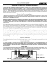
Figure 14D