


Hearth & Home Technologies • Heat-Zone-240V Air Duct Kit • 299-900D • 7/10 3
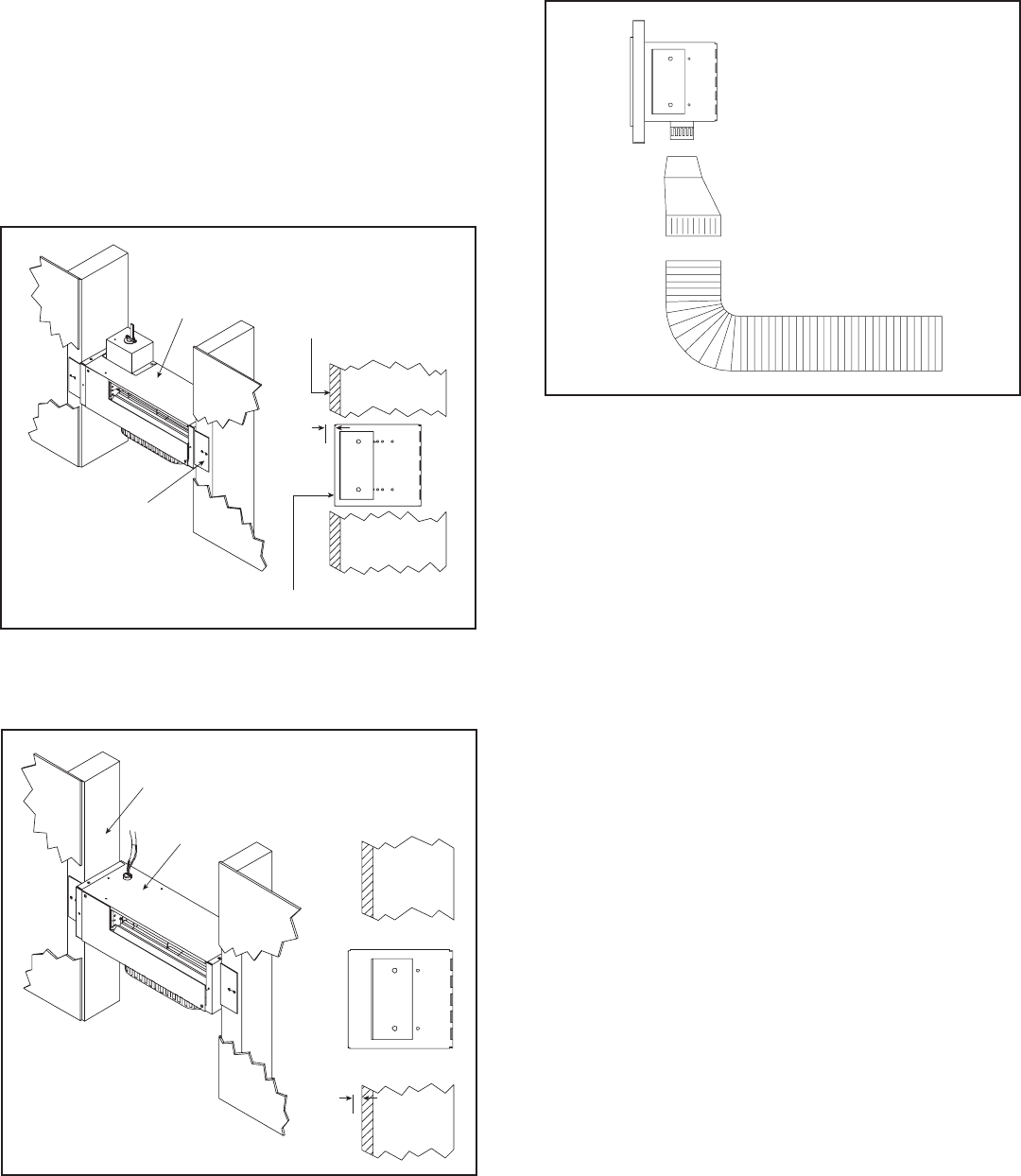
FAN HOUSING
ADJUSTABLE
MOUNTING BRACKET
FINISHED SURFACE
FRONT OF FAN HOUSING
6 mm
3.
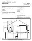
Determine the location for the air register/fan housing
as-
sembly. Cut a 127 x 346 mm hole between framing
members (wall studs or fl oor joists).
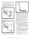
4. Mount and secure the fan housing assembly to framing
members so the front surface is 6 mm below the fi n-
ished wall or fl oor surface. Use the adjustable mounting
brackets and screws provided in the kit. See Figure 4.
NOTE: The brackets can be rotated 180º and mounted
to the back side of the 2 x 4 if necessary.
NOTE: If the fan housing is installed in a 2 x 4 wall, the
front of the housing will protrude approximately 13 mm out
of the wall. See Figure 5.
Figure 4
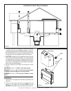
5. Install the air duct run. NOTE: Fold outer poly layer of
fl exible duct back to maintain clearance to combustibles
on the fi replace. Secure liner to the collar with clamp.
Figure 5
FAN HOUSING
2 x 4 WALL
13 mm
ROUND AIR DUCT: Attach the 152 mm round air duct
(supplied in the kit) to the heater collar and run the duct to
the fan housing. Attach the round-to-oval adapter to the
fan housing and the air duct to the adapter. See Figure 6.
OVAL AIR DUCT: Attach the round-to-oval adapter to
the heater starting collar and a 152 mm oval duct to the
adapter. Complete the duct run and attach the oval duct
to the fan housing. NOTE: 152 mm metal oval air duct is
NOT provided with this kit but can be purchased from a
heating or air conditioning ventilation supplier.
ROUND and OVAL DUCT: A combination of 152 mm round
and 152 mm oval air duct can be used in the duct run. Oval
duct components must be purchased from a heating or air
conditioning ventilation supplier.
NOTE: Support duct at intervals of no greater than four
feet with no more than 1/2 in. sag between supports or as
required per local code. Secure the duct so that clearance
to the outer wrap of the fi replace is maintained.
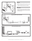
6. Install a wall switch in a convenient location. This switch
will control the HEAT-ZONE-240V fan operation. When
using the AUX300CE in the IPI Plus system, the AUX1
or AUX2 can control the output and ON/OFF function in
place of a separate wall switch. Note that the RC300
remote is needed.
7. Wire 240 VAC service TO the wall switch and FROM the
wall switch to the fan junction box. Use wire connectors to
secure the 240 VAC service wires to the hot and neutral
fan wires and screw the 240 VAC ground wire to the fan
junction box. See Figure 8 for isolated control wall switch.
See Figure 9 for IPI Plus with auxiliary control.
8. Screw the fan junction box to the fan housing.
9. Screw the register adapter frame and the air register to
the fan housing. See Figure 7.
10. Complete the heater installation per instructions.
Figure 6