


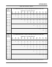
INSTALLATION
7
PLUMBING
An adhesive backed paper template is shipped with
the unit and is used to locate the sink strainer holes.
Use the following procedure to install the heater unit
to the holding vessel.
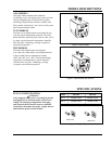
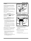
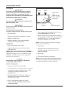
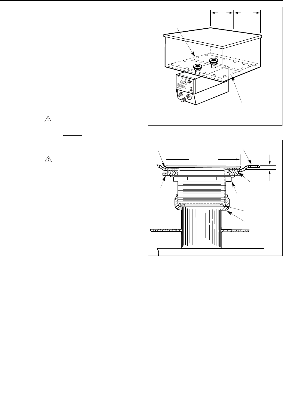
NOTE: The FR2 heater should be positioned with
no more than 3' (914 mm) on either side when mounted
under holding vessel. See Figure 6. A perforated water
baffle (not supplied with unit) must be used to distribute
the heated water properly.
NOTE: Use one FR2 for a Hot Food Table
up to 6' (1829 mm) long. Over 6' (1829 mm) minimum
2 units required.
CAUTION
Unit is not weatherproof. For safe and proper
operation locate the unit indoors
where the ambient
air temperature is constant and is a minimum
of 70°F (21°C).
CAUTION
Do not use extension pipes on the inlet and outlet
connections on heater units. Poor performance
or unsafe conditions may occur.
1. Expose the adhesive back of the paper template
and stick the template on the bottom of the holding
vessel. Center the template with the words “Front
Cover” positioned against the front inside wall
of the vessel.
2. Center punch and drill a 3/4" (19 mm) pilot hole
at each of the two center marks on the template.
3. Remove the template and cut a 2" (51 mm) diameter
hole at each pilot hole location using a standard
#ATV1756 Greenlee cutter.
NOTE: If a #ATV1756 Greenlee cutter is not available,
use a standard Greenlee 1-1/2" conduit cutter #500-6978,
which is slightly under 2" (51 mm) diameter. File
or ream holes as necessary to 2" (51 mm) diameter
required for mounting sink strainers.
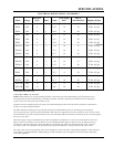
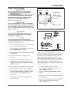
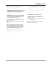
4. See Figure 7. In each of the holes, install a male
threaded sink strainer with a thin gasket between
the strainer flange and the bottom of the
holding vessel.
5. Install two thick gaskets at the underside
of the holding vessel along with a thin fiber gasket,
and secure finger tight with the nut.
3" (76 mm)
Thin rubber washer
Thick rubber
washers
(Qty. 2)
Thin fiber
washer
1/8" (3 mm)
offset
Sink or tank
Nut
Union nut
Union Gasket
Figure 7. Installing Sink Strainer
6. Attach the heater to the strainers loosely
with the union nuts and 1-3/4" (45 mm)
rubber gaskets.
NOTE: Make sure rubber gaskets are positioned inside
the union nuts and are not crimped.
7. Tighten nuts on strainers securely.
8. Tighten union nuts securely.
9. Fill the holding vessel with water and check for leaks.
Form No. HHM-1103
Figure 6. Hydro-Heater Water Baffle
3'3'
3/4" (19 mm) holes
around periphery on
6" (152 mm) centers
Dotted line
indicates the position of
perforated water baffle
3/4" (19 mm) high baffle
with divider wall between
inlet and outlet
(914 mm)
MAX
(914 mm)
MAX