7
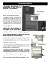
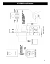
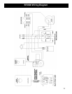
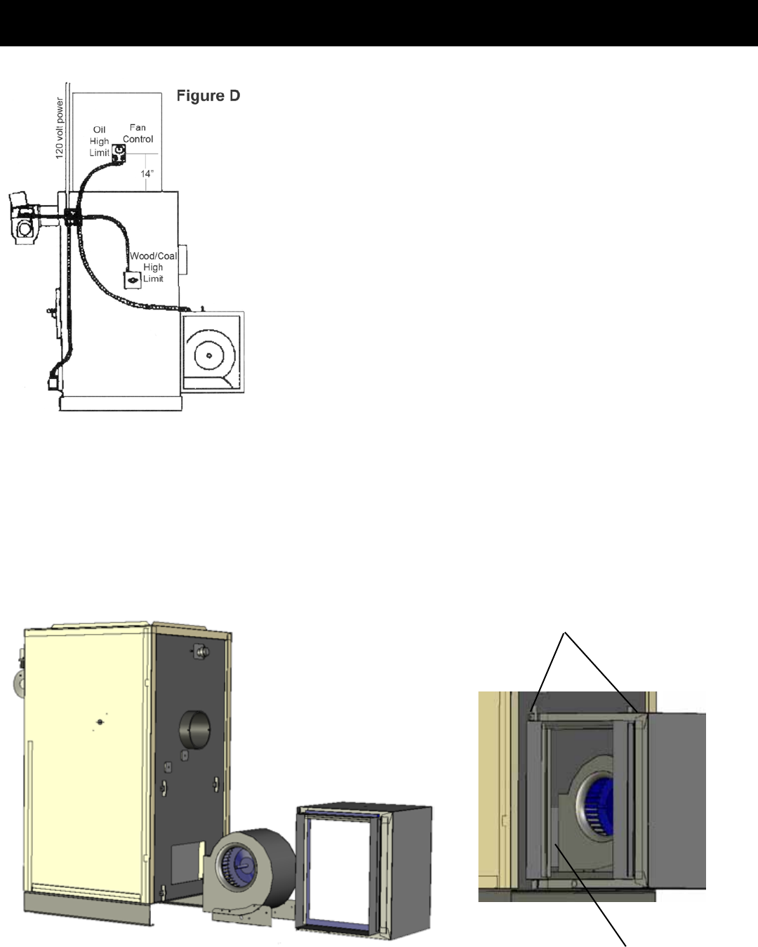
This gure represents the model SF2600 furnace. It’s intention is to
represent the approximate location of the various controls. This drawing
may also be used as a reference for wiring and control spacing. Please
note that this drawing is for reference only. Specic installations will vary.
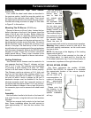
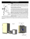
Position the lter box between the brackets on the rear of the furnace,
with the bottom of the box resting on the ange at the bottom of the
furnace. Insert the mounting clips into the bracket slots to secure the lter
box. (see Figure 2) Next, install the blower brackets onto the blower being
sure to install the rubber feet into the brackets. NOTE: On the SF3500,
install the blower mount and blower before the lter box.
Next, position the blower in the lter box, centered behind the
inlet hole and allow approximately 1/8 in. space between the rear of the
furnace and the blower outlet. Now, install the lter rail onto the lter
box. NOTE: The lter rail is best installed on the side toward the shaker
handle, so that any pipes from the hot water coil do not interfere with lter
installation or removal.
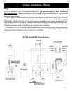
NOTE: Before proceeding with the installation of the access door, it is suggested that the wiring be completed.
The access door is installed by slipping the ange on the bottom of the access door over the bottom rail of the
lter box opening, then push the top of the door against the top of the lter box opening and secure with a sheet
metal screw.
Filter box mounting clips
1/8 in. space between
blower and furnace


