


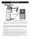
8
Furnace Installation - Wiring
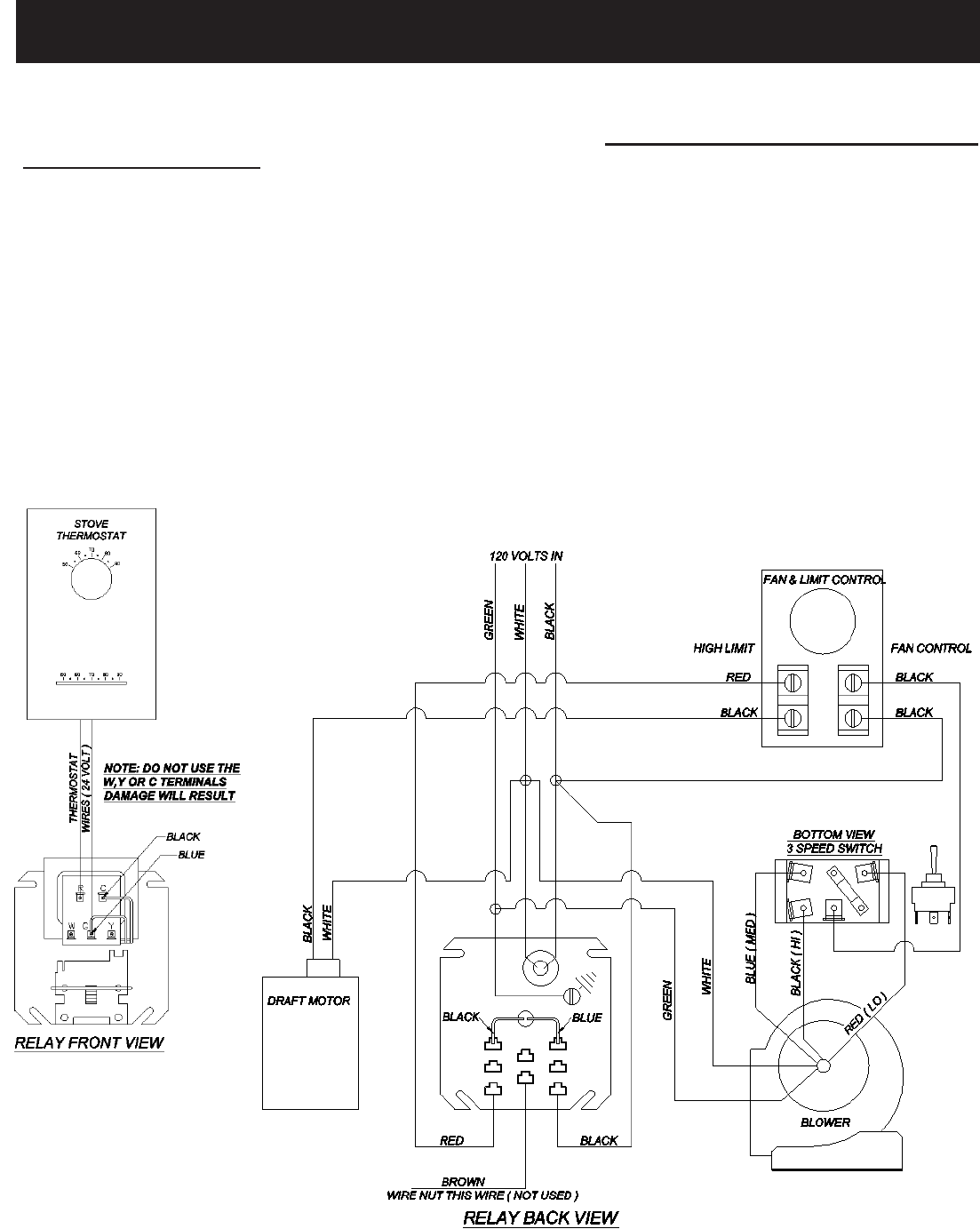
Wiring
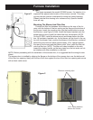
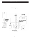
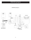
Beforebeginninganywiring,studytheappropriatewiringdiagramforyourunit.Alsoreferbacktog-
ures C or D for an example of what the completed job will look like. It is your reponsibility to follow all state
and local electrical codes. Locate the best place to route the power for the blower, and drill a 7/8” hole in the
lterbox.Thisholesizewillaccomodatea“romex”connector.Attachtheblowerandpowerwiresasshownon
the appropriate wiring diagram.
Once you have the plenum installed, the fan control with high limit switch can be installed. The Fan
control/high limit switch is packaged with a jumper between the two sets of terminals inside. REMOVE THE
JUMPER WIRE INSIDE THE FAN CONTROL. The fan control should be installed in the right side of the ple-
num and 12 to 18 inches above the top of the furnace. A separate conduit should be run from the fan control to
the junction box.
Mount the thermostat in a central location of the area you want to heat. Run two wires to the junction
box, from the heating terminals on the thermostat. 22 gauge or thicker wire is acceptable.
The next step is to run a 120 volt line from your breaker panel to the junction box. Attach all wires ac-
cording to the corresponding wiring diagram, and install the relay into the junction box. DO NOT TURN ON
THE BREAKER UNTIL ALL WIRING IS COMPLETE AND THE RELAY IS SECURED.
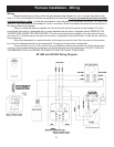
SF1500 and SF2500 Wiring Diagram