


6
CHIMNEY & VENTING
Types Of Chimneys
The chimney is one of the most important, yet most
neglected and misunderstood portions of any solid
fuel burning stove installation. Do not connect this
stove to a chimney ue serving another heating de-
vice.
THE STOVE MUST BE CONNECTED TO ITS OWN
TILE-LINED FLUE. A MINIMUM FLUE SIZE OF 8” X
8” IS NECESSARY FOR PROPER OPERATION.
UNDER NO CIRCUMSTANCES SHOULD A MANUAL
FLUE DAMPER BE INSTALLED IN THE SMOKE
PIPE BETWEEN THE STOVE AND THE CHIMNEY.
NO DAMPER, HEAT SAVER OR AUTOMATIC VENT
DAMPER DEVICE SHOULD BE INSTALLED IN OR
ON THE SMOKE PIPE.
CAUTION: THE CHIMNEY MUST BE A CLASS “A”
CHIMNEY, IN GOOD OPERATING AND CLEAN
CONDITION.
NOTE: THE USE OF ALUMINUM TYPE “B” GAS
VENT FOR SOLID FUELS IS UNSAFE AND PRO-
HIBITED BY THE NATIONAL FIRE PROTECTION
AGENCY CODE.
There are three types of class “A” chimneys:
1. Masonry with tile liner, to include brick or stone. It
must be supported on grade level foundation.
2. Insulated, manufactured chimney, listed or certied
by a national test agency.
3. Triple-wall metal class “A” chimney, listed or certi-
ed by a national test agency.
If your masonry chimney has not been used for some
time, have it inspected by a qualied person. If a listed
or certied manufactured chimney is to be used, make
certain it is installed in accordance with the manufac-
turer’s instructions and all local and state codes.
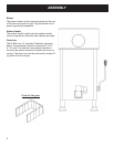
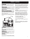
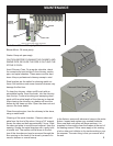
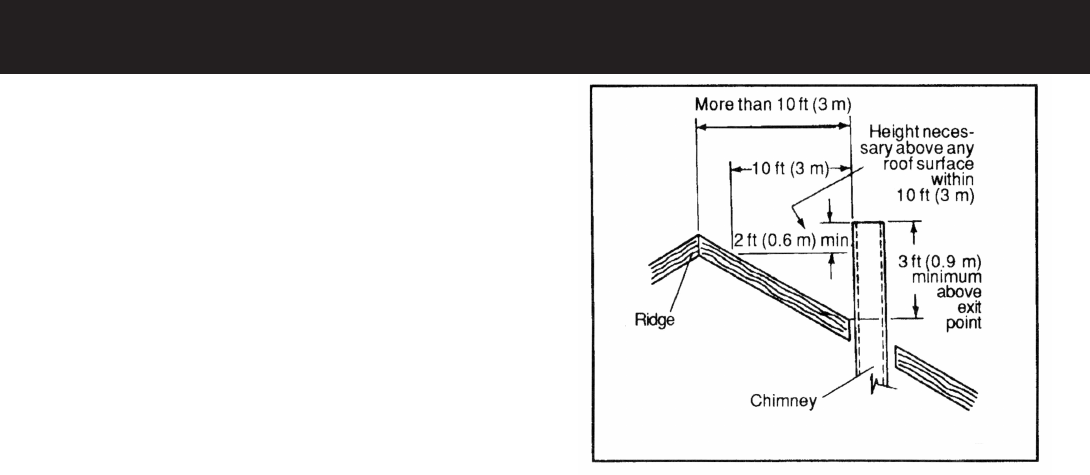
The minimum recommended height for solid fuel
chimneys is 16 feet from the stove collar. The chimney
must be two feet higher than anything within ten feet.
It also must extend three feet above the point where it
intersects or exits the roof line.
In order to have a properly operating solid fuel heat-
ing system, the chimney must be capable of provid-
ing the necessary draft. The minimum required draft
is .06 inches of water column (W.C.). This must be
measured using a draft gauge. If the chimney cannot
supply this constant draft, the stove will not operate
properly. A barometric damper may be used and prop-
erly adjusted to compensate for excessive draft only.
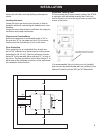
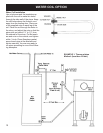
IMPORTANT: When you measure the the draft, the
stove must be operating with sufcient time given for
the stove and chimney to warm. Burn for at least thirty
minutes. The draft reading is best taken 18” up from
the center of the ue outlet, in the connector pipe. Drill
a hole in the pipe for the meter tube, and ll it with a
screw or silicone when done with the test.
IMPORTANT: The connector pipe must be 24 gauge
or thicker.
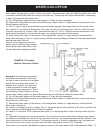
When connecting the ue pipe to the stove, the rst
section should be installed inside the stove collar. It
should be secured to the collar with, at least, three
screws or rivets.
Do not pass the connector pipe through a wall or
ceiling without rst checking with your local codes. If
allowed, use only approved pass-thru methods.
NOTE: All horizontal runs of venting should have a 1/4
inch of rise per foot of length.
Use no more than two 90° elbows in the connector.
If a barometric damper is needed, to compensate for
excessive draft, install it only in a vertical section of
vent pipe.
The three foot, two foot, ten foot rule