


11
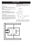
WATER COIL OPTION
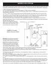
Example 1: Thermo-siphon Method. This is the simplest and most economical method, providing the existing
water heater (storage tank) is within 10 feet of the stove. The water inlet, where the Temp/Pressure relief valve
is located, must be higher than the top leg of the water coil. The storage tank should be elevated, if necessary,
to allow for proper thermo-siphon action.
A). Turn off the water heater and the water supply to it. Drain the tank completely.
B). Remove the Temp/Pressure relief valve and discard. Install a short ¾” nipple and tee (1) along with a new
Temp/Pressure relief valve.
C). Run ¾” copper tubing, along with the necessary ttings, between the storage tank and the top leg of the
coil. Install a ¾” vent elbow and automatic “oat type” air vent (2) in the high point of the line. Within two feet
of the top leg of the coil, install a 150 lb. pressure relief valve (7). Run ¾” tubing from the release exit of both
relief valves, downward (3) so that the hot water may escape in the event of over-heating.
D). Remove the drain valve, at the bottom of the storage tank. Install a ¾” nipple and tee, and reinstall the
drain valve to the tee (4). Run ¾” copper tubing, with the necessary ttings, between the drain/tee combination
and the lower leg of the coil.
After all of the connections are com-
pleted, you can rell the tank. Restore
power to the water heater ONLY after
the tank has been completely relled.
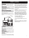
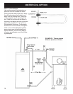
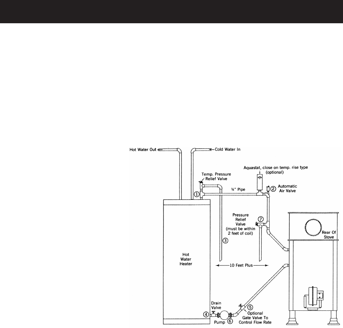
Example 2: Circulating pump method.
Used when the distance is more than
ten feet or when the stove is on a higher
level than the existing water heater. In
addition to a circulator, you may want
to add a aquastat to control the pump
according to water temperature. This is
not necessary if the circulator is left run
continuously. Another option is a gate valve placed near the circulator to control the rate of ow.
A). Turn off the water heater and the water supply to it. Drain the tank completely.
B). Remove the Temp/Pressure relief valve and discard. Install a short ¾” nipple and tee (1) along with a new
Temp/Pressure relief valve.
C). Remove the drain valve, at the bottom of the storage tank. Install a ¾” nipple and tee, and reinstall the
drain valve to the tee (4).
D). Install a circulating pump (6) as shown. Run ¾” copper tubing from the circulator to the lower leg of the coil.
This is where the optional gate valve (5) can be installed.
E). Install a ¾” tee and a 150 lb. pressure relief valve (7) in the top leg within 2 feet of the top outlet of the wa-
ter coil.
F). Complete the copper line by running it back to the tee at the top of the water tank, making sure to install a
vent elbow and automatic air vent (2) at the high point of the line. The optional aquastat can be installed in this
line a maximum of six feet from the stove. The aquastat must be a “close on temperature rise” type and must
be wired and set to turn on the circulator when the water temperature reaches 120˚ Farenheit.
The system is now ready to be relled and power restored to the water heater ONLY after the tank is lled.
EXAMPLE 2: Circulator
Method. (more than 10 feet.)