


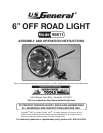

Page 5SKU 95811
For technical questions, please call 1-800-444-3353.
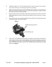
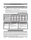
Required: Switch/Fuse (not included) rated at 15 amps or larger.
Battery
Switch
Red Positive wire (not included)
Fuse
Black Ground Wire (6)
Figure 2
The red Positive wire (not included) from the Light is the “HOT” wire. Use a pin con-
nector or in-line splice connector (both not included) to connect the Off Road Light
to your vehicle’s electric wiring system. When using an in-line splice connector, it
is not necessary to strip the wires. The wiring diagram in Figure 2 will give you a
basic idea of how to set up the wiring.
The red Positive wire (not included) runs from the light to the Fuse, then to the
switch. From there it is wired to the electrical wiring running to the battery. The
Black Ground Wire (6) (included) must make contact with a metal surface to assure
proper grounding.
Attach the Red Positive wire (not included) to a switched power wire (e.g. tail light
or the low beam of the head light). Then wrap the connection with water proof tape
(not included).
Lay the connector for the switch (not included) of the wiring harness into the driver’s
compartment through the fire wall. Use a hole already made for the purpose of
handling other wires.
Connect the wire to the switch. Find a flat surface near the dashboard. Use double
sided tape to secure the switch in the place you want it to remain. Be sure to tape
any extra wiring to the underside of the dashboard, or to the inside of the engine
compartment away from moving parts. Do not leave extra wire hanging loose in
either the driver’s compartment or the engine.
Reconnect the battery and turn on the switch to test the whole system. If the Light
does not operate properly, check the fuse/ground wire/battery connection/switch/
lamp connection/relay all the way back to the Off Road Light to make sure every-
thing is connected properly.
Loosen the Light adjustment screws. With the system on, adjust the Light’s angle
until the proper angle is obtained. Retighten all the screws.
7.
8.
9.
10.
11.
12.
13.