


5
PU
ELECTRIC HEATER KIT
RD
BL
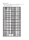
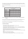
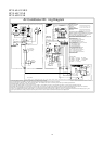
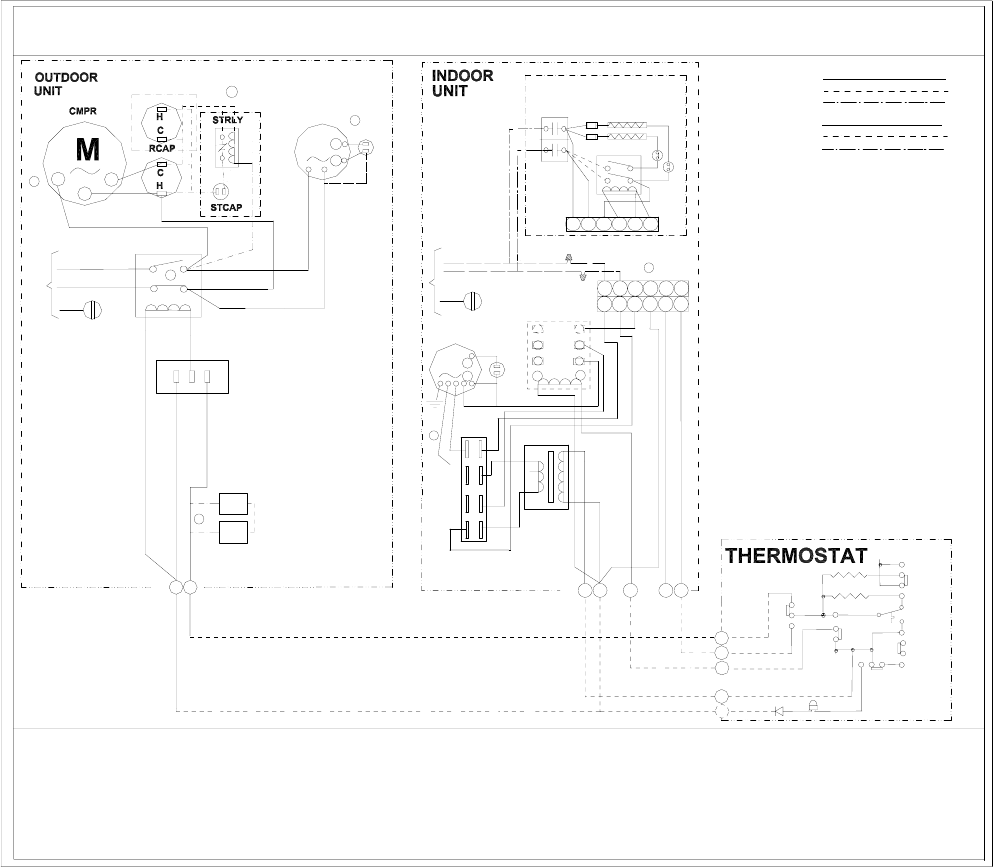
Air Conditioner Wi ring Diagram
1) Confirm system selection. Optional com ponents m ay be field or factory installed.
2) If LPS and/or HPS not installed or removed, a jumper wire must be present across circu it for syst em to operate.
3) For proper system operation, consul t indoor unit and outdoor unit installation inst ructions to confirm syst em match up and blower speed selection.
4) Alternate double pole contac tor used on some syst ems.
5) Only one start assist method to be used at a time, consul t outdoo r unit inst allation instructions for application information. Use only factory approved accesso ries.
6) Optional OFM components m ay connect capac itor common and motor common, for reciprocating compres sor ther e may have cran kcase heat er consult outdoor unit inst allation
instruct ions for details.Select the running capacitor(one or dual)and connect.If IFM or OFM only have one capacit or wire,connect Com wire to capacitor.
7) Indoor unit shipped w ithout optional electric heater kit. To inst all optional heater kit,remove po wer pig tail up to 9 pin plug. Install heater kit and connect with mating 9 pin plu g. Run
system power connect ions directly to electric heater kit power terminals. Consult heater kit inst allation instructions for complete details.
RD
24VAC COMMON
COMPRESSOR
BL
YL
208/230V
60Hz 1PH
C
BL
BL
YL
YL
Y
2
YL
P3
P2
P1
6
RD
R
L1
GND
L2
BK
BK
WH
C
S
CC
4
RD
YL
2
1
NC
Optional
Low & High
Pressur e
Switches
LPS
HPS
Compressor
Protect 3 Min.
Time Delay
BCAP
RD-LO
RD
L2
RD
OR
BK-HI
M
IBM
3
GR
PU
L1
BK
BK
R
S
BR
BR
208
COM
BL
R
TRAN
COM
230
7
BL
5
3
RD
NO
GR
8
6
4
OFM
M
BK
PU
PU
BR
6
S
R
BR
L1
L2
GND
60Hz 1PH
208/230V
WH
BK
BCR
1
BK
2
RD
BRK
BK
L2
RD
RD
FL
L1
BK
FL
USE COPPER CONDUCTORS ONLY
WARNING CABINET MUST BE PERMANENTLY GROUNDED
AND ALL WIRING TO CONFORM TO I.E.C.,N.E.C.,C.E.C.,
C.L.C. AND LOCAL CODES AS APPLICABLE.
REPLACEMENT WIRE MUST BE THE SAME GAGE AND
INSULATION TYPE AS ORIGINAL WIRE.
COMPONENT CODES
BCR - BLOWER CONTROL RELAY
BCAP - RUN CAPACITOR BLOWER MOTOR
CC - COMPRESSOR CONTACTOR
CCH - CRANKCASE HEATER (OPTIONAL)
CHS - CRANKCASE HEATER SWITCH (OPTIONAL)
CMPR - COMPRESSOR
HPS - HIGH PRESSURE SWITCH
LPS - LOW PRESSURE SWITCH
IBM - INDOOR BLOWER MOTOR
OFM - OUTDOOR FAN MOTOR
RCAP - RUN CAPACITOR COMPRESSOR
RVS - REVERSING VALVE SOLENOID
STCAP - START CAPA CITOR (OPTIONAL)
STRLY - START RELAY (OPTIONAL)
STRTH - START THERMISTOR (OPTIONAL)
TRAN - TRANSFORMER
230/208 SELECTABLE
R
H
S
-
1
COLOR CODES
BK - BLACK BL - BLUE GY - GRAY
BR - BROWN GR- GREEN OR - ORANGE
PU - PURPLE RD - RED VI - VIOLET
WH - WHITE YL - YELLOW
INDOOR FAN CONTROL
HEAT CONTROL
C
R
Y
W
G
WH
C
BL
G
W2
BL
BR
W
CA
RHS-2
TS
ON
AUTO
LED
F
A
N
COOL
OFF
HEAT
S
W
-
2
HA
COOL
OFF
HEAT
S
W
-
1
LINE VOLTAGE
FACTORY STANDARD
FIELD INSTALLED
OPTIONAL
LOW VOLTAGE
FACTORY STANDARD
FIELD INSTALLED
OPTIONAL
WH
PU
2
2
BK
1
1
RD
3
3
4
BL
3
5
BR
5
5
BL
4
4
7
BR
6
6
6
WH
BK
OPTIONAL
BK
RD
RD
RD
RD
TL
TL
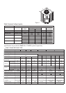
RESISTANCE
14
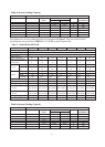
HC18-60A1VAR/S
HC18-60C1VAR
HC18-60D1VAR