23
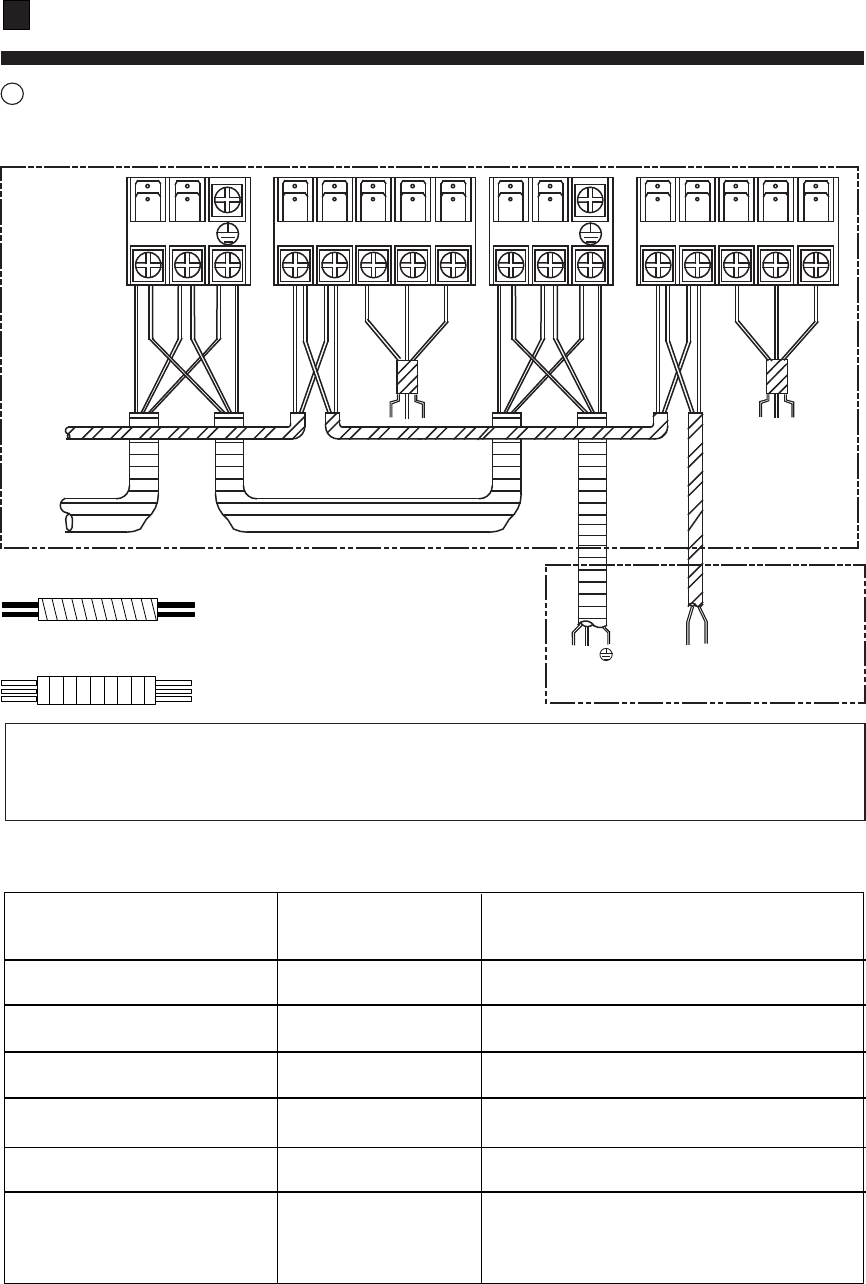
4 Wiring of indoor unit
The distance between the signal wires and the power cabes should be at least 50mm.
C
BA
Q
P
1(L) 2(N) 2(N)1(L)
P
Q
A B
C
L N
C1 C2
To other
indoor unit
To wired controller(A,B,C)
To outdoor unit
(P Q)
06
FAILURE CODE
(CHECK THE WIRED
REMOTE CONTROLLER)
TROUBLE SHOOTING
(indoor unit)
Failure code
*
*
*
*
*
Waring:
1.Incorrect address setting will cause abnormal to the system.
2.Communication cable must be use sheilded type.
Communication cable (Shield wire):
H05RN-F 2X1.5 mm
2
Power cable : H05RN-F 3G 2.5 mm
2
POSSIBLE REASONS
Faulty temperature sensor Tai
01
Sensor disconnected, or broken, or at wrong
position, or short circuit
Faulty temperature sensor Tc1
Sensor disconnected, or broken, or at wrong
position, or short circuit
Faulty temperature sensor Tc2
03
Sensor disconnected, or broken, or at wrong
position, or short circuit
Faulty temperature sensor Tm
04
Sensor disconnected, or broken, or at wrong
position, or short circuit
Faulty EEPROM on indoor
unit PCB
05
Faulty indoor unit PCB
Abnormal communication
between indoor and outdoor unit
Wrong connection, or the wires be
disconnected, or wrong address setting of
indoor units, or faulty power supply or faulty
PCB
02
Instructions to installation


