


Installation Procedures
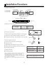
ELECTRICAL WIRING
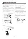
(1) The power source capacity must be the sum of the
room air conditioner current and the current of other
electrical appliances. When the current contracted
capacity is insufficient, change the contracted
capacity.
(2) When the voltage is too low and the air conditioner
is difficult to start, contact the power company the
voltage raised.
CAUTION
TEST RUNNING
1. CHECK ITEMS
(1) INDOOR UNIT
(1) Is operation of each button on the remote control
unit normal?
(2) Does each lamp light normally?
(3) Do not air flow direction louvers operate normally?
(4) Is the drain normal?
(2) Air filter removal and cleaning, and how to use
air louvers.
(3) Give the operating and installation manuals to
the customer.
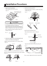
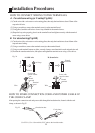
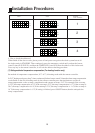
(1) Always use a special branch circuit and install a special
receptacle to supply power to the room air conditioner.
(2) Use a circuit breaker and receptacle matched to
the capacity of the room air conditioner.
(3) The circuit breaker is installed in the permanent wiring.
Always use a circuit that can trip all the poles of the
wiring and has an isolation distance of at least 3mm
between the contacts of each pole.
(4) Perform wiring work in accordance with standards so
that the room air conditioner can be operated safely
and positively.
(5) Install a leakage circuit breaker in accordance with the
related laws and regulations and electric company
standards.
WARNING
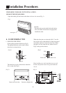
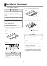
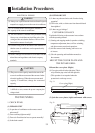
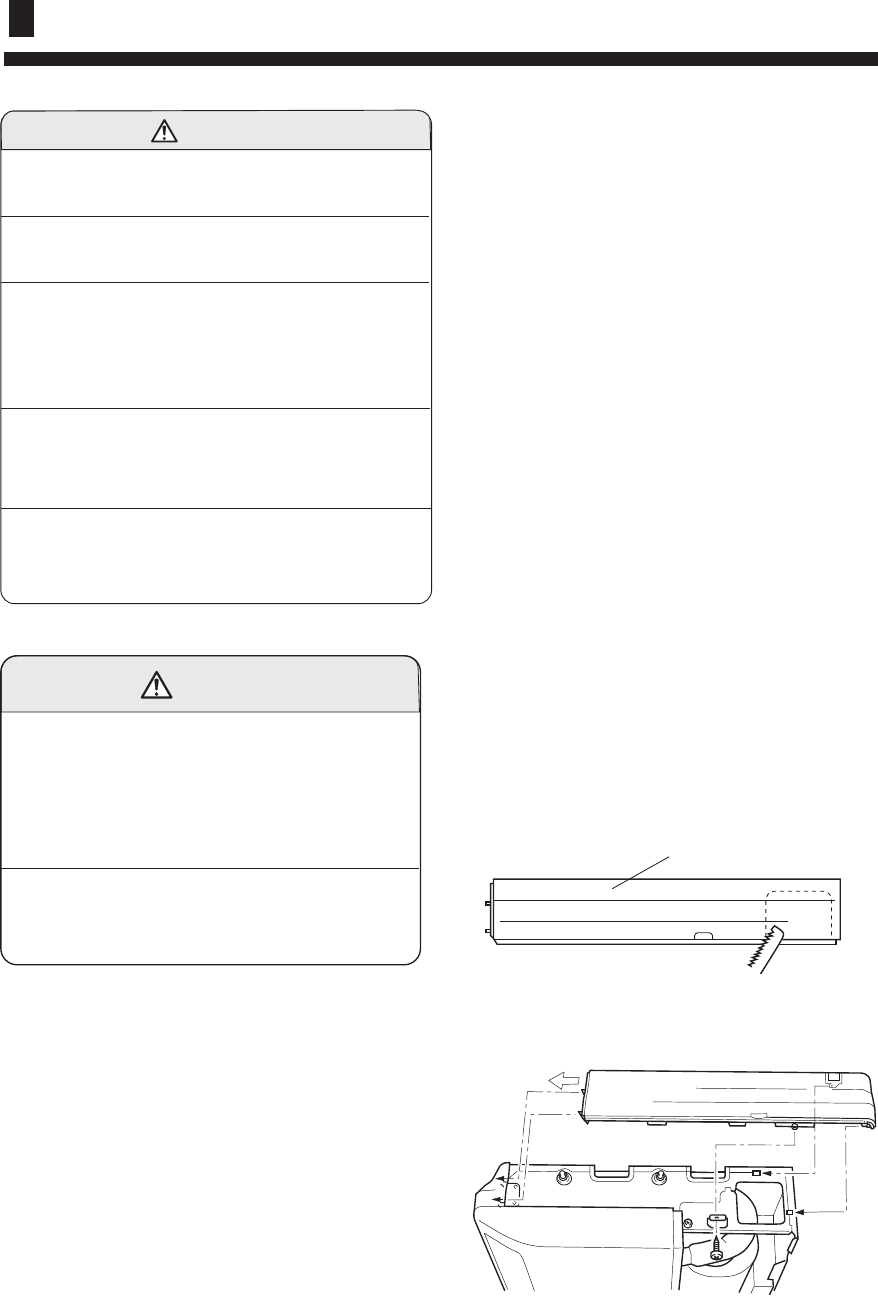
MOUNT THE COVER PLATE AND
THE INTAKE GRILL
19
(2) OUTDOOR UNIT
(1) Is there any abnormal noise and vibration during
operation?
(2) Will noise, wind, or drain water from the unit disturb
the neighbors?
(3) Is there any gas leakage?
CUSTOMER GUIDANCE
Explain the following to the customer in accordance
with the operating manual:
(1) Starting and stopping method, operation switching,
temperature adjustment, timer, air flow switching,
and other remote control unit operations.
1.Mount the cover plate. (Right)
(1) Cut a pipe exit hole in the right plate. This is
only when the pipe exits from the right side.
(This operation is not required when the
protrusion is on the top or rear.)
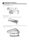
Fig. 31
Cover plate (Right)
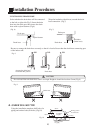
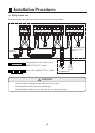
(2) Join the cover plates (right) and mount with screws.
Fig. 32