– 8 –
Chimney
Be sure that the chimney is sufficiently high and large
enough to meet the specifications of the burner unit
installed. Check that there is sufficient draft for the proper
burning of oil. At least -0.015 in. (-0.381mm) water column
of over-fire draft is recommended.
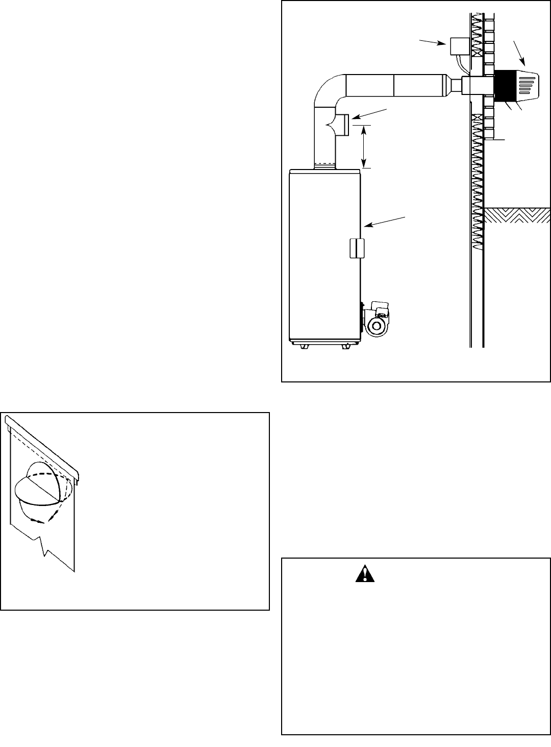
Blocked Vent Safety Switch
Oil-fired water heaters installed in Canada must be fitted
with the blocked vent safety switch supplied with your
heater. The installation procedure is given below. For further
details and information refer to the instruction sheet supplied
with the switch. (Not required for JWF307V.)
Installation
1. Pierce a 16mm (5/8 in.) dia. hole into the flue pipe
305mm to 457mm (12 to 18 in.) from the breech con-
nection of the water heater. Remove one of the securing
nuts from the pipe of the safety switch. Tighten the other
securing nut onto the pipe as far as possible.
2. Insert the threaded pipe end into the pierced hole, then
install the securing nut, which was removed in step 1,
and tighten securely.
CAUTION:: Turn "OFF" the electrical supply to the water
heater when wiring safety switch.
3. Wire the safety switch in series with L1 of the electrical
supply (see Figures 9, 10 & 11). Install and route wiring
in an accordance with “Canadian Electrical Code Part
1 (C22.1)” and any applicable local codes.
CAUTION: If for any reason the system has shut down dur-
ing operation, the cause of the system failure should be
investigated and corrected before resetting the safety switch
and re-starting the system.
Power Venting
Models JWF307, JWF507 and JWF657 may be power vent-
ed with a Field SWGII 4HD Power Venter. The following con-
trol kits may be used with the SWGII 4HD:
CK 61 Electronic Post Purge.
CK 62 Thermally Activated Post Purge.
Installation of Power Venter
The “Installation Code for Oil-Burning Equipment (CSA
B139-04)” or “Standard for the Installation of Oil-
Burning Equipment (NFPA 31)”, local codes and the man-
ufactures instructions should be adhered to in all installa-
tions of the water heaters and power venters. A draft regula-
tor must be used in conjunction with the installation of the
power venter (see “Draft Regulator”). Consult the applicable
codes to calculate total equivalent vent pipe length, the
straight runs of pipe and the equivalent length of pipe for
each fitting.
Burner Installation
General
The installation of these units shall be in accordance with
the “Installation Code for Oil-Burning Equipment (CSA
B139-04)” or “Standard for the Installation of Oil-
CK SERIES
CONTROL KIT
DRAFT
REGULATOR
OIL FIRED
WATER
HEATER
SWG II 4HD
POWER
VENTER
Figure 6 POWER VENTING
BEND DOWN
WHEN MODEL JWF307 IS TO BE FIRED AT
THE MAXIMUM RECOMMENDED RATE OF
0.75 GPH, THE FLUE BAFFLE MUST BE
ALTERED AS IN THE DIAGRAM. BOTH HALF
DISCS MUST BE BENT FLAT AGAINST THE
BODY OF THE BAFFLE.
THIS IS REQUIRED TO ALLOW FLUE GAS
PASSAGE AT THE HIGHER FIRING RATE.
Figure 5 BAFFLE MODIFICATION (JWF307)
This installation must be performed by a
qualified Oil-Burner Technician in accor-
dance with these instructions and diagrams.
The installation and maintenance of the
water heater must follow all of the instruc-
tions in preceding sections of this manual.
Improper installation can cause injury or
property damage. Heater failure that is a
result of the heating system is not covered
by warranty.
WARNING
SEE MANUFACTURER’S
INSTRUCTIONS


