


-7-
All leak testing must be done with a soapy water solu
-
tion or equivalent leak test liquid. Never use a match or
open flame to test for gas leaks. A fire or explosion
could result.
The appliance and its individual shut–off valve must be
disconnected from the gas supply piping system during
any pressure test of that system at test pressures in
excess of 1/2 PSIG (3.5 kPa).
The appliance must be isolated from the gas supply
piping system by closing its individual manual shut–off
valve during pressure testing of the gas supply piping
system at test pressures equal to, or less than 1/2
PSIG (3.5 kPa).
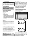
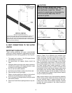
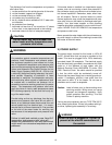
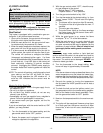
GAS
VALVE
MANUAL GAS
SHUT-OFF
GROUND-JOINT
UNION
SEDIMENT
TRAP
3” - 5”
Figure 7
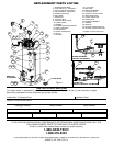
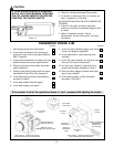
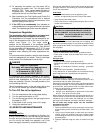
IV) WATER PIPING
General
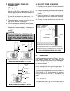
Pipes and fittings must be installed as shown in Figure
8. Note that the dip tube is in the cold water fitting (right
hand side) of the heater. Some heaters may have heat
trap fittings installed in the HOT and COLD water con-
nection of the heater. These appear generally like plugs
in the fitting, the cold fitting being colored blue and the
hot fitting, red or pink. Do not attempt to pry these
“plugs” loose or damage them.
When attaching sweat fittings to the heater, do not
apply heat to the nipples of the water heater because
the nipples contain a plastic liner. Sweat the adaptor to
a length of tubing – usually 6” – 8” long minimum,
before fitting the adaptor to the water connections.
Hot and Cold Water Connections
It is good practice to install unions at the hot and cold
water connection of the heater. The cold water connec-
tion must have a shut–off valve installed so that the
heater can be isolated from the house supply for ser-
vicing.
When the water connections have been completed, fill
the tank with water.
To fill the tank, open an upstairs hot water faucet. Open
the cold water valve in the cold water line to the heater.
Make sure the drain valve of the heater is closed. When
an uninterrupted stream of water without apparent air
bubbles flows from the hot water faucet, the tank is
filled. Close the hot water faucet.
Check for leaks, and repair as necessary.
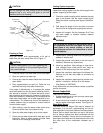
SHUT-OFF VALVE
UNION
PIPE LENGTH 6” - 8”
(150 - 200 mm)
ADAPTOR 3/4” NPT
DIPTUBE
(COLD SIDE ONLY)
WATER PIPING DETAIL
Figure 8
NOTE: VENTING DETAILS
HAVE BEEN REMOVED
FOR CLARITY
Temperature and Pressure Relief Valve
Water heaters have the temperature and pressure relief
valve factory–installed for protection against excessive
temperature and/or pressure.
Any replacement valve must not exceed the tempera-
ture and pressure rating of the original valve, and must
meet the latest edition of ANSI Z21.22 • CSA 4.4 the
Standard for “Relief Valves and Automatic Gas Shutoff
Devices for Hot Water Supply Systems.”
To prevent bodily injury, hazard to life or damage to
property, the relief valve must be allowed to discharge
water in the event of excessive temperature and/or
pressure in quantity, should circumstances demand.
CAUTION
Before filling the tank, ensure that a properly rated
temperature and pressure relief valve is installed in
the designated fitting.
See following T&P Valve section.