– 8 –
SPECIAL NOTE ON PROPANE FUEL:
L.P. GAS IS HEAVIER THAN AIR
Should there be a leak in the system, the gas will settle at
FLOOR LEVEL. Basements, crawl spaces, closets and areas
below ground level will serve as pockets for the accumulation of
the gas.
BEFORE LIGHTING, SNIFF AT FLOOR LEVEL. IF YOU
SMELL GAS, FOLLOW THESE RULES.
1. Get all people out of the building.
2. DO NOT light matches.
3. DO NOT touch electrical switches (on or off).
4. DO NOT use an electrical fan to remove gas from area.
5. SHUT OFF GAS at the L.P. tank outside of the building.
6. IMMEDIATELY call the L.P. Gas Company or the fire
department from a neighbor’s phone. Ask for instructions. Before
hanging up, give your name, address and telephone number.
7. DO NOT go back into the building. If help is coming, wait for
it outside the building.
OUT OF FUEL
When your L.P. tank runs out of fuel, turn off gas at all gas
appliances. After L.P. tank is refilled, all appliances must be re-lit
according to the manufacturers instructions.
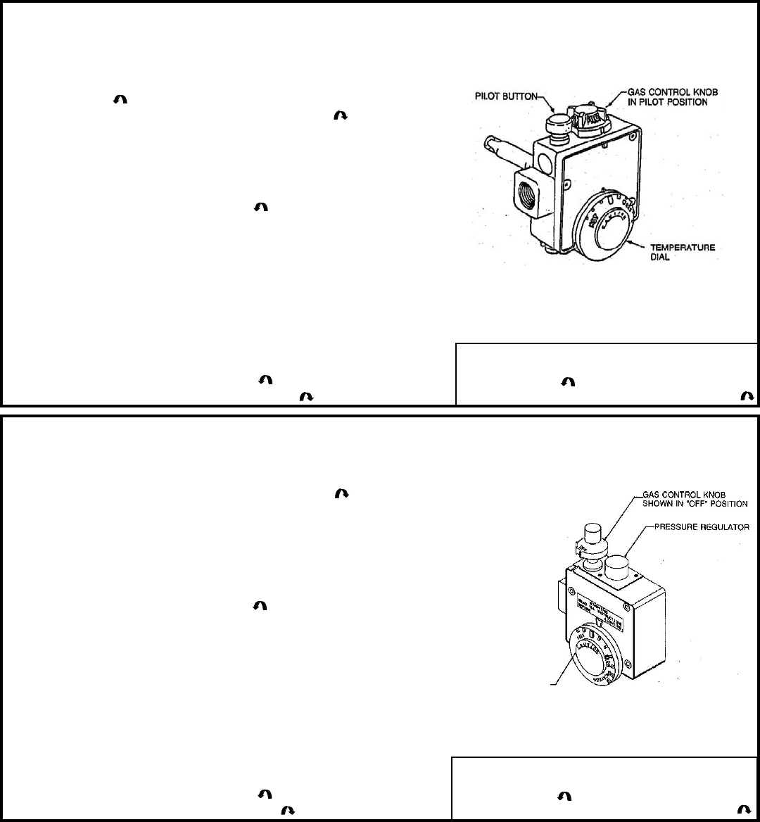
LIGHTING INSTRUCTIONS FOR HEATER WITH “ROBERTSHAW R110” GAS
CONTROLS
WARNING: Should overheating occur or the gas supply fail to shut off, turn off the manual gas valve to the appliance.
LIGHTING INSTRUCTIONS FOR HEATER WITH “ROBERTSHAW 220R” GAS
CONTROLS
WARNING: Should overheating occur or the gas supply fail to shut off, turn off the manual gas valve to the appliance.
1. STOP! Read all safety labels on the water heater before operation.
2. Set the thermostat to the lowest setting. Rotate dial on front of control
counterclockwise.
3. Rotate gas control knob on top of thermostat clockwise to “OFF” position.
4. Wait 5 minutes to clear out any gas. If you smell gas, STOP! Follow
instruction “B” above on page 7. If you do not smell gas, go to the next step.
5. Remove outer door. Slide inner combustion door to right.
6. Find pilot. Follow aluminum tube from the “right-underside” of the gas
thermostat. The pilot is adjacent to burner.
7. Turn gas control knob counterclockwise to “PILOT” position.
8. Use a lit match held securely with an extension device, or a long stem igniter.
While holding the ignition source at the pilot, depress the red pilot set button
(upper left) to light the pilot. Continue to hold the pilot set button for about 1
minute after pilot is lit. Release pilot set button and it will pop up. Pilot should
remain lit.
•If knob does not pop up when released, stop and immediately call your
service technician or gas supplier.
•If the pilot will not stay lit after several tries, turn the control knob to “OFF”
and call your service technician or gas supplier.
9. Slide inner combustion door to left and replace outer door.
10. Turn gas control knob counterclockwise to “ON” position.
11. Set the thermostat to desired setting clockwise.
1. STOP! Read all safety labels on the water heater before operation.
2. Rotate gas control knob on top of thermostat clockwise to “OFF” position.
3. Set the thermostat to lowest setting.
4. Wait (5) minutes to clear out any gas. If you then smell gas, STOP! Follow
instruction “B” above on page 7. If you don’t smell gas, go to the next step.
5. Remove outer door. Slide inner combustion door to right.
6. Find pilot. Follow aluminum tube from the “right-underside” of the gas
thermostat. The pilot is adjacent to burner.
7. Turn gas control knob counterclockwise to “PILOT” position.
8. Use a lit match held securely with an extension device, or a long stem igniter.
While holding the ignition source at the pilot, depress the gas control knob to
light the pilot.
9. After pilot lights, keep knob depressed for at least 60 seconds to properly
heat thermocouple and activate safety valves.
10. If the pilot does not remain lit wait at least 10 minutes and repeat steps 1-9.
•If knob does not pop up when released, stop and immediately call your
service technician or gas supplier.
•If the pilot will not stay lit after several tries, turn the control knob to “OFF”
and call your service technician or gas supplier.
11. Slide inner combustion door to left and replace outer door.
12. Turn gas control knob counterclockwise to “ON” position.
13. Set thermostat to desired setting clockwise.
To Turn Off the Gas Control
1. Set the thermostat dial to the lowest setting. Turn
counterclockwise.
2. Turn gas control knob “OFF”. Rotate clockwise.
To Turn Off the Gas Control
1. Set the thermostat dial to the lowest setting. Turn
counterclockwise.
2. Turn gas control knob “OFF”. Rotate clockwise.
ROBERTSHAW R110 GAS CONTROL
ROBERTSHAW 220R GAS CONTROL
TEMPERATURE DIAL


