


2
FILLING TANK
1. Close the drain valve, and then open a hot water faucet.
2. Open the cold water supply valve.
3. When water runs out of the hot faucet, the tank is full.
4. Check the system for leaks.
NOTE: When filling, avoid water spillage. Do not allow the insulation of
the heater to get wet as water can cause electrical malfunction.
DRAINING TANK (completely)
If the power is to be turned off during the cold season and the tank is exposed
to freezing temperatures, the water heater must be drained. Water will expand
when it freezes and can damage the heater.
Completely drain as follows:
1. Make sure the electrical supply to the water heater is “OFF”.
2. Turn off cold water supply.
3. Connect a garden hose to the end of the drain valve and direct this to a
point lower than the heater.
4. Open a hot water faucet.
5. Open the drain valve on the heater – drain, keeping the drain valve open
during the shutdown period.
6. To refill the heater, see ‘Filling Tank’ section.
INSTALLATION CHECK LIST Check Here
1. Are the fuse and wire sizes correct?
2. Is the certified relief valve installed?
3. Are you sure that in case of water leakage, the building,
furniture, carpeting or other property will not be damaged?
4. Has the relief valve been piped to a suitable drain point?
5. Is the relief valve discharge unobstructed?
6. Is the heater completely filled with water?
7. Is the cold supply valve open?
If the answer to the above are yes, turn on the power and enjoy all the hot
water you need, all the time.
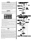
RELIEF VALVE REQUIREMENTS
CAUTION To reduce the risk of excessive pressures and temperatures in this
water heater, install temperature and pressure protective equipment required
by local codes. It should be no less than a combination temperature and
pressure relief valve certified by a nationally recognized testing laboratory
that maintains periodic inspection of production of listed equipment or
materials, as meeting the Requirements for Relief Valves and Automatic Gas
Shut-off Devices for Hot Water Supply Systems, ANSI Z21.22-latest edition.
This valve must be marked with a maximum set pressure not to exceed the
marked MAXIMUM working pressure of the water heater (150 PSI). Install
the valve into an opening provided and marked for this purpose in the water
heater, and orient it or provide tubing so that any discharge from the valve
will exit only within 6 inches above, or at any distance below the structural
floor and cannot contact any live electrical part. The discharge opening must
not be blocked or reduced in size under any circumstances.
The end of the relief pipe opening should terminate near a floor drain or other
suitable location not subject to blocking or freezing. DO NOT thread, plug or
cap the relief pipe opening.
TEMPERATURE & PRESSURE RELIEF VALVE
Inspect the relief valve annually to ensure proper operation. This involves
opening the valve to check that water is able to flow freely, and that there are
no blockages. Warning: THE WATER WILL BE HOT and its flow can be
forceful. Provide a bucket or drainage for the expelled water. Lift the lever
and let it snap shut. The water should stop immediately.
If the valve does not function properly, it MUST be replaced. In systems
where the relief valve discharges periodically, this may be due to thermal
expansion causing pressure build up. See ‘Pressure Build-Up (Thermal
Expansion’ section.
TEMPERATURE ADJUSTMENT
In order to reduce the risk of scald injury, thermostats are factory set a
t
120°F (49°C). The thermostats operate automatically. They can be adjusted
to provide warmer or cooler water temperature. The setting of 120°F (49°C)
has been proven to be most satisfactory from the standpoint of operational
costs and safety. We recommend you keep the thermostats adjusted to
120°F (49°C). If adjustments are made set both thermostats to the SAME
setting (if applicable).
TEMPERATURE LIMIT CONTROL
For safety, a non-adjustable high limit temperature switch will shut off the
power when excessive water temperatures are reached. This switch must be
re-set manually. See ‘Trouble-Shooting’ section.
WARNING BEFORE ATTEMPTING ANY ELECTRICAL
REPAIRS OR REPLACEMENTS, TURN OFF POWER TO THE
WATER HEATER. CHECK WITH A VOLTAGE TESTER AT
TERMINAL 1 AND 3 OF THE LIMIT CONTROL THAT POWER IS
INDEED OFF. FAILURE TO DO SO MAY RESULT IN ELECTRIC
SHOCK AND/OR ELECTROCUTION OF THE PERSON DOING
THE WORK.
If water temperature adjustment is required:
1. Turn the electrical supply to the water heater “OFF”.
2. Remove the access door(s), and turn back insulation.
3. Adjust the thermostat(s) to the water temperature desired (if a two-
thermostat system exists, set both thermostats at the same temperature).
4. Repack the insulation and replace access door(s).
5. Turn the electrical supply to the water heater “ON”.
ELEMENT REPLACEMENT
1. See ‘Draining Tank’ section to remove water from the heater.
2. Turn the electrical supply to the water heater “OFF”.
3. Remove the access door(s), and turn back insulation.
4. Disconnect wires from heating element terminals.
5. Unscrew the element using a 1½” socket wrench or tool number S1008,
available from your water heater distributor.
6. Replace element with new one, taking care that sealing gasket is in the
groove of element flange.
7. Re-connect wiring, and replace Di-Electric shields.
8. Repack insulation over thermostat(s), and replace access door(s).
9. Fill tank with water BEFORE turning ELECTRICITY on. See ‘Filling
Tank’ section.
THERMOSTAT REPLACEMENT
1. Turn the electrical supply to the water heater “OFF”.
2. Remove the access door(s), and turn back insulation.
3. Disconnect wires from thermostat(s).
4. Lift prongs off bracket and slide thermostat up and out.
5. Replace in reverse order, taking care that thermostat(s) is flush against
the tank.
6. Repack insulation over thermostat(s), and replace access door(s).
7. Turn the electrical supply to the water heater “ON”.
CATHODIC PROTECTION: ANODE MAINTENANCE
Your water heater has been supplied with an anode rod that protects the tank
from corrosion. As the rod works, it slowly dissolves over time and must be
replaced. If the anode is less than 3/8” diameter, or any exposed bare core,
replace. Depending on water conditions, an anode can last from one to ten
years. Many localities treat their water, which can have significant effect on
the life of your heater. Water conditioning such as over softening ca
n
accelerate the rate at which the anode rod is consumed. Rapid depletion ca
n
leave a heater unprotected causing a premature failure. As with any water
heater, it is good practice to check the anode annually to see if it needs
replacing.
CAUTION
FOR YOUR SAFETY, BE AWARE THIS WATER HEATE
R
IS CAPABLE OF PRODUCING HOT WATER AT A
TEMPERATURE SUFFICIENT ENOUGH TO CAUSE
SCALDING INJURY. READ INSTRUCTIONS CAREFULLY
BEFORE OPERATING THIS UNIT. INCREASING THE
THERMOSTAT SETTING ABOVE THE PRE-SET
TEMPERATURE MAY CAUSE SEVERE BURNS AND
CONSUME EXCESSIVE ENERGY. HOTTER WATE
R
INCREASES THE RISK OF SCALD INJURY.
150°F (66°C) – 2 SECONDS
140°F (60°C) – 6 SECONDS
130°F (54°C) – 30 SECONDS
FAILURE TO INSTALL A LISTED ¾” TEMPERATURE -
PRESSURE RELIEF VALVE WILL RELEASE THE
MANUFACTURER FROM ANY CLAIM WHICH MIGHT
RESULT FROM EXESSIVE TEMPERATURES AND
PRESSURES.