


1
PLUMBING
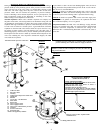
1. The cold water inlet is identified at the top of the heater (unless bottom
entry). The hot water connection is also identified at the top of the heater.
Install a shut-off valve in the cold line approximately 3’ from the inlet to
the heater where it is in convenient reach. This valve is for emergency
shut-off and MUST be kept open during the operation of the heater.
2. All nipples contain a plastic lining to minimize corrosion (cold inlet
nipples have double sleeve, hot outlet nipples have a single sleeve). Do
not apply heat to these nipples when making solder connections. Sweat a
piece of tubing to adapter before fitting adapter to nipple.
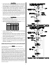
3. A combination Temperature and Pressure relief valve MUST be installed.
In some cases it is necessary that a Tee be fitted in the top of the heater
which allows the temperature probe to reach into the top of the tank. See
diagram on page 4. No shut-off valve of any kind is permitted between the
tank and the relief valve. The outlet of the relief valve must be piped to a
drain or fixture, and must terminate within 6” of the floor.
ELECTRICAL
1. Check to see that the element marking and nameplate data do correspond
with the electric service available.
a) The junction box where electrical connections are made is located near
the top of the heater, near the upper access door.
2. Install a circuit directly from the main fuse box. This circuit must be the
right size for the length of run and the load (see chart below).
RECOMMENDED FOR AMPERAGE
MAX. VOLTS
MAX.
WATTS
120V 208V 240V
1500 20A 10A 10A
3000 35A 20A 20A
3500 40A 20A 20A
4500 30A 25A
5500 35A 35A
The heater must be well grounded.
3. A ground wire must run from the green ground screw provided at the
electrical connection point in the heater junction box to the ground
connection at the service panel.
4. Adequate fusing must be provided at the service entrance as required by
local codes and/or electric utility having jurisdiction. This can be
accomplished with either a circuit breaker or fuse block in the service
panel or a separate disconnect switch, so that electric power can be shut
off easily when working on the heater.
5. Final connections are made at the junction box in the heater. Access to the
junction box is obtained by removing the cover near the knockouts.
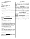
6. The heater you have received is internally wired. A specific wiring
diagram is located inside the upper door or for certain models on the
rating plate. All wiring is color-coded and connections must be made as
shown in the wiring diagram
MAKE SURE HEATER IS COMPLETELY FILLED WITH WATER
BEFORE POWER IS TURNED ON. SEE ‘FILLING TANK’ SECTION.
WIRING
TWO WIRE CIRCUIT FOR NON-SIMULTANEOUS OPERATION.
SINGLE HIGH LIMIT.
The basic operation of a two thermostat system (upper and lower) on a
electric water heater of 240 volts is as follows:
Only one element will come on at any one time. This is known as a flip/flop
system. On a 240-volt water heater, there will always be 120 volts to both
elements. The thermostat will direct the second leg of the 120-volt to the
element to complete the 240 volts required for energizing the element.
Initial Start Up: When the tank is full of cold water, the upper thermostat
will take priority and the top portion of the water will heat up to the setting of
the thermostat. Once that temperature has been reached, the thermostat will
then flip down the 120 volts to the lower thermostat. The thermostat switch
closes and the bottom portion of the tank heats up until the water reaches the
setting on that thermostat. At this point the tank will be full of hot water.
Normal Operation: When hot water is being used, cold water enters the
bottom of the heater (either bottom feed or by diptube), and the bottom
element will begin to heat the cold water. If lots of hot water has been used,
the upper thermostat will take priority and the top portion of the heater will be
heated. Once heated, the thermostat will flip down to the lower thermostat to
heat the lower portion.