


- 5 -
General
Applicable Codes
In addition to the installation instructions found in this man-
ual, the water heater must be installed in accordance with
all local and provincial or state codes or, in the absence of
local and provincial or state codes, with the latest edition of
“Canadian Electrical Code” (in Canada) or NFPA-70
“National Electrical Code” (in USA).
The requirements of these documents must be carefully fol-
lowed in all cases. Authorities having jurisdiction shall be
consulted before installations are made. Check your phone
listings for the local authorities having jurisdiction over your
installation.
Important: Installation and service must be performed by
a qualified service technician.
FAILURE TO FOLLOW THE INSTRUCTIONS IN
THIS MANUAL MAY RESULT IN DEATH, SERIOUS
BODILY INJURY AND/OR PROPERTY DAMAGE.
THOROUGHLY READ ALL INSTRUCTIONS
BEFORE YOU ATTEMPT TO INSTALL, OPERATE
OR MAINTAIN THIS HEATER.
Location Requirements
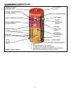
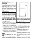
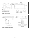
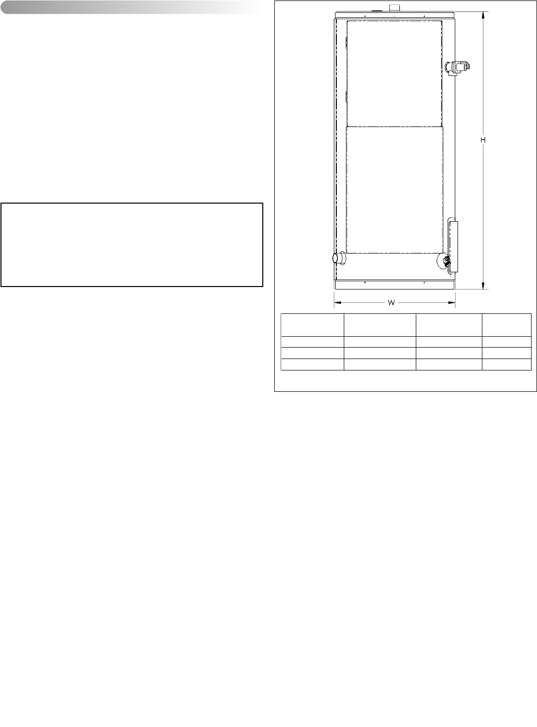
Refer to Figure 2 to determine the size of the various mod-
els of the water heater.
1. A clear space of 457mm (18 in.) should be allowed in
front of the heater to allow access to the controls and
elements.
2. A clearance of 305mm (12 in.) is sufficient clearance
from the top of the heater to adjacent surfaces.
3. It is suggested that the heater be located in the center of
the water system or close to the point-of-use requiring
the most hot water.
4. The water heater should be located in an area not sub-
ject to freezing temperatures.
5. Water heaters located in unconditioned spaces (i.e.,
attics, basements, etc.) may require insulation of the
water piping and drain piping to protect against freezing.
6. The drain and controls must be easily accessible for
operation and service.
This water heater is not intended for space heating
applications.
Temperature and Pressure (T&P) Relief
Valve
All water heaters must be installed with a proper tempera-
ture and pressure relief valve. In the United States this valve
must be design certified by a nationally recognized testing
laboratory that maintains periodic inspection of the produc-
tion of listed equipment or materials as meeting the require-
ments for Relief Valves and Automatic Shut-off Devices for
Hot Water Supply Systems, ANSI Z21.22.
Important: Only a new temperature and pressure relief
valve should be used with your water heater. Do not use an
old or existing valve as it may be damaged or not adequate
for the working pressure of the new water heater. Do not
place any valve between the relief valve and the tank.
The T&P Valve:
• Must be connected to an adequate discharge line.
• Must not be rated higher than the working pressure
shown on the data plate of the water heater.
The Discharge Line:
• Must not be smaller than the pipe size of the relief valve
or have any reducing coupling installed in the discharge
line.
• Must not be capped, blocked, plugged or contain any
valve between the relief valve and the end of the dis-
charge line.
• Must terminate a maximum of 152mm (6 in.) above a
floor drain or external to the building.
• Must be capable of withstanding 121°C (250°F) without
distortion.
State of California
Note: The water heater must be braced,
anchored, or strapped to avoid moving dur-
ing an earthquake. Contact local utilities for
code requirements in your area.
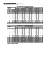
Capacity
(litres/USG)
Height
(meters/inches)
Width
(meters/inches)
Nipple Size
(inches)
184 / 50 1.31 / 51.5 0.57 / 22.25 1.5
280 / 80 1.56 / 61.5 0.62 / 24.25 1.5
420 / 119 1.65 / 64.75 0.73 / 28.5 1.5
FIGURE 2: Rough-in Dimensions
IV) INSTALLATION