


5
5. ACTUATOR CONNECTIONS
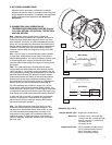
Electrical and/or pneumatic connections to damper
actuators should be made in accordance with wiring and
piping diagrams developed in compliance with applicable
codes, ordinances and regulations (see Electrical
Guidelines).
6. CONNECTION AND OPERATION OF
TEMPERATURE RESPONSE DEVICES (Fusible
Link, RRL OPTION, OCI OPTION, TOR OPTION,
and PRV OPTION)
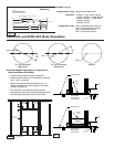
RRL - Dampers will be supplied with a fusible link
temperature response device, as a standard. An optional
thermostat type temperature response device may have
been installed. The device is a RRL (resetable link device),
which only incorporates one thermostat and therefore the
damper remains closed as soon as its sensor temperature
is reached. The RRL does not contain blade indication
switches. Refer to Fig. 4 on page 5 for wiring of the RRL
thermostat.
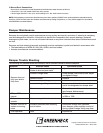
OCI - The OCI (open or closed indicator) option contains
a single pole, double throw switch used to indicate the
damper blade position. The switch provides a positive open
or closed signal when used in conjunction with remote
indicator lights. Refer to Fig. 5 on page 5 for wiring of the
OCI option.
TOR - The TOR (temperature override device) option
incorporates two thermostats with fixed settings (usually
165°F and 350°F). The primary sensor (the sensor with the
lower temperature setting) can be bypassed by an external
electrical signal allowing the damper to reopen until the
temperature reaches the setting of the secondary sensor
(the sensor with the higher temperature setting). When
the temperature of the secondary sensor is exceeded the
damper closes and remains closed thereafter (Fig. 6)
The TOR assembly also contains a single pole, double
throw switch used to indicate damper blade position. The
switch provides a positive open or closed signal when used
in conjunction with remote indicator lights. See page 6, Fig.
6 for wiring of the TOR thermostats and indicator switches.
If either the TOR or the RRL is ordered with a pneumatic
actuator, an EP switch is required with an appropriate
electric power circuit to allow the electric thermostat to
control the pneumatic actuator.
PRV - The PRV (pneumatic relief valve) option is heat
responsive device used with pneumatic actuators. This
can be used in place of EP switch where a RRL is used.
The PRV activates when temperature in excess of the
temperature of the fusible link are detected. When the
fusible link melts, air from the actuator is exhausted to
close the dampers. Pneumatic actuators are to be piped
per local code.
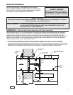
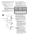
Fig. 3
L1
M
L2
ELECTRIC DAMPER
ACTUATOR OR PNEUMATIC
SOLENOID VALVE
PRIMARY TEMP
SENSOR
ELECTRICAL CAPACITY = 10 AMP @ 120 / 240
VA
C
BLACK
ORANGE
P
NC
BLACK
WHITE/RED
Fig. 4
RRL Wiring
RATINGS (Fig. 4 & 5)
Integral Switch Type: Single Pole, double throw
Electrical: 10 Amps,
1
/3 hp, 120 or 240 Vac
1
/2 Amp, 125 Vdc;
1
/4 Amp 250 Vdc
5 Amps, 120 Vac “L” (lamp load)
1.0 Amps, 24 Vac
1.5 Amps, 24 Vdc
Temperature Limit: 165° F (standard primary sensor)
212°
F (optional primary sensor)
250°
F (secondary sensor)
350º F ( secondary sensor)
-
%".1&3
*/%*$"503
-*()54
-
$-04&%104*5*0/0'5)&%".1&3
"#-6&."3,&3*/%*$"5&5)&
5)&48*5$)8*3&483"11&%8*5)
/05&
:&--08
&-&$53*$"-$"1"$*5:".1!7"$
:&--08
:&--08
:&--08
/0
/0
4
4
#:05)&34
OCI Wiring
Fig. 5