


4
2. SLEEVE LENGTH AND WALL/FLOOR THICKNESS
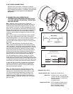
Insert the damper assembly into the prepared opening, to
appropriate depth (see Page 3, Fig. 1).
Recommended maximum and minimum insertion depth
can be exceeded if:
1) the operation of the damper actuator is not
impeded and
2) the
C
L
of the damper blade remains within the
plane of the wall/floor
IMPORTANT SAFETY DANGER! : To avoid
causing death or serious bodily harm to building
occupants, do not insert screws into the damper
frame unless used for duct connection within 2
in. of the frame end.
The sleeve may extend a maximum of 16 in. beyond the
wall or floor on the actuator side of the damper and a
maximum of 6 in. on the opposite side.
3. DUCT TO SLEEVE CONNECTIONS
Dampers are supplied with sleeves and actuators from
the factory and can be installed without the need for
additional field installed sleeves.
Gauge of factory furnished sleeve determines the
type of duct to sleeve connections required (see table
below). Any duct connection other than the breakaway
connections are considered rigid.
Type of Duct to
Sleeve Gauge Duct Dimension Sleeve Connection
Permitted
10 ga. (0.138 in.)
14 ga. (0.075 in.)
24 in. max. dia. Rigid or Breakaway
16 ga. (0.060 in.)
20 ga. (0.036 in.) 24 in. max. dia. Breakaway only
Sleeve thickness must not be less than the gauge of the connecting
duct.
UL Standard 555 requires all ducts to terminate at fire damper
sleeves.
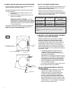
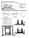
4. SECURING THE DAMPER/SLEEVE ASSEMBLY
TO WALL AND FLOOR OPENINGS
Damper assemblies must be installed in wall/floor
openings using a single retaining plate on either
side of the wall/floor or by using a retaining plate
on both sides of the wall/floor. The use of a second
retaining plate is allowed, but is not necessary. A
single retaining plate is provided with the dampers. A
second retaining plate can be ordered as an option.
The outside dimension of the supplied retainer plate is
nominal dia. + 4.50”.
• The retaining plate(s) will open up for easy
installation when the clamping screw is
loosened. If necessary, remove the clamping
screw and nut (see
Fig. 2).
(IMPORTANT: The clamping mechanism should
face away from the wall/floor). Retainer plate(s)
are designed to mount flush to the wall/floor
and hold the damper in the wall/floor opening.
• Place the damper and attached retainer plate
into the wall/floor opening.
• If a second retaining plate is being used, secure
it on the opposite side of the wall/floor
DO NOT POSITION RETAINER PLATE(S) IN
FRAME GROOVE
• Verify position, blade orientation, and actuator
clearance then tighten the retainer plate
clamping screws. The retainer plate(s) must
overlap the wall/floor opening a minimum
of 1 inch. Secure the retainer plate(s) to the
wall using appropriate fasteners (minimum #8
sheet metal screws) at the four corners of each
retainer plate when two retainer plates are used
and also within
3
⁄4 in. of the center of each plate
when one retainer plate is used.
0QFOJOHJO.JO
JO.JO5ZQ
'BTUFOFST
$MBNQJOH
4DSFX
/VU
3FUBJOJOH
1MBUF"TTFNCMZ
$MBNQJOH4DSF
X
.JOJNVN8BMM'MPPS0QFOJOH
/PNJOBM%JBJO
Fig. 2