


10
Engineering Data
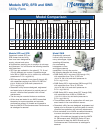
Selection
The first consideration in any fan
selection is the amount of air to be
moved and the resistance to this air
movement. Air volume requirements are
established through specific codes or
accepted industry standards. Once the
air volume is known, system resistance
can be determined by summing up the
losses through the system components.
Duct layout, duct size, coils, filters,
dampers, and fan accessories all affect
system resistance. ASHRAE Guide and
Data Books and manufacturer’s data
on individual system components are
common sources of information available
to the system designer.
In most applications, several fans may
meet the required airflow and system
resistance conditions. An optimum fan
selection requires evaluation of alternative
fan types and fan sizes, as they relate
to initial cost, operating cost, available
space, and allowable sound levels. The
relative importance of these facts varies
with each system.
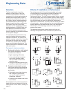
Two types of wheels are available:
1. Backward-inclined or airfoil wheels
turn at twice the speed of forward-
curved fans and feature:
•Higher operating efficiencies
•A non-overloading horsepower
curve which reaches a peak
near the middle of the normal
operation range
•Stronger wheel design allowing for
operation at higher static pressures
2. Forward-curved wheels typically
have lower performance capabilities
compared to the backward inclined
and contain:
•Overloading type wheel (meaning
that changes in performance
can result in significant brake
horsepower changes)
•Forward-curved wheels have lower
sound levels
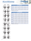
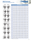
Comprehensive air performance data for
these utility fans can be found in the fan
tables and fan curves section, starting on
page 15.
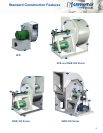
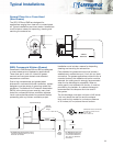
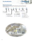
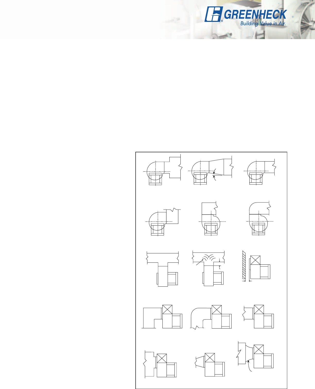
Effects of Installation on Performance
Fan ratings presented in the performance tables and curves
of this catalog are in accordance with AMCA Standard 210
“Laboratory Methods of Testing Fans for Aerodynamic
Performance Rating.” The AMCA test procedure utilizes an open
inlet and a straight outlet duct to assure maximum static regain.
Any installation with inlet or discharge configurations that deviate
from this standard may result in reduced fan performance.
Restricted or unstable flow at the fan inlet can cause pre rotation
of incoming air or uneven loading of the fan wheel yielding large
system losses and increased sound levels. Free discharge or
turbulent flow in the discharge ductwork will also result in
system effect losses.
The examples below show system layouts and inlet and
discharge configurations which can affect fan performance.
GOOD
POOR
POOR
FAIR
7
o
MAX.
POOR
FAIR
POOR
FAIR
One
Impeller
Dia.
GOOD
Should be at least
1/2 Impeller Dia.
FAIR
Not Greater than
60
o
Including Angle
POOR
POOR
FAIR
GOOD
POOR
Turning
Varies