


26
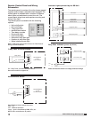
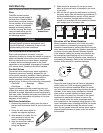
Model ERVe Energy Recovery Unit
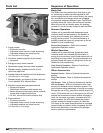
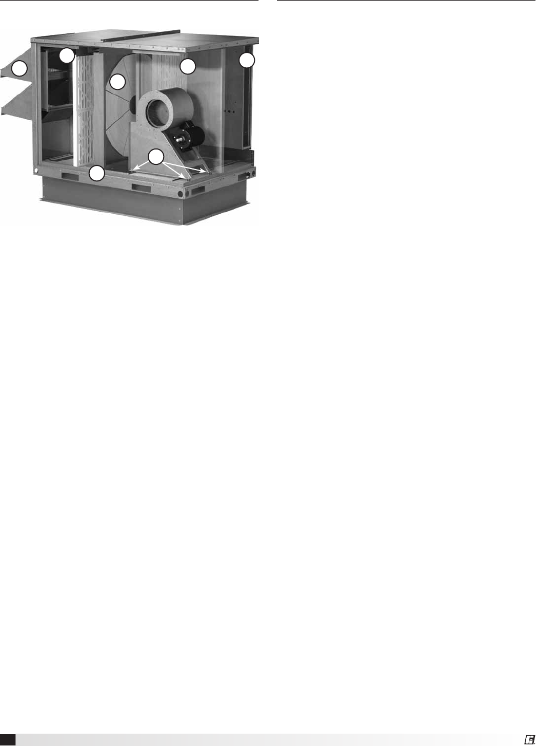
Parts List
1. Supply blower
• Forwardcurvedfan
• Adjustablemotormountforbelttensioning
• Adjustablesheavesforspeedcontrol
Not depicted on this image
2. Vibrations isolators (quantity 4 per blower)
• Neoprene
3. Energy recovery wheel cassette
4. Removable energy recovery wheel segments
5. Standard supply weatherhood with 2-inch
aluminum mesh filter
6. Standard exhaust weatherhood with birdscreen
Not depicted on this image
7. Standard supply and exhaust air filter racks for
2-inch pleated, 30% efficient filters
8. Electrical control box (standard features)
• Singlepointpower
• Disconnectinterlockedwithaccessdoor
• Motorstartersforthesupplyblower,exhaust
blower and energy wheel motors
• 24VAC,controlcircuitwithterminalstrip
9. Exhaust blower
• Forwardcurvedfan
• Adjustablemotormountforbelttensioning
• Adjustablesheavesforspeedcontrol
Not depicted on this image
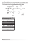
Sequence of Operation
Basic Unit
The ERVe units are prewired such that when a call
for outside air is made (via field supplied 24 VAC
control signal wired to unit control center), the supply
fan, exhaust fan and energy wheel are energized
and optional motorized dampers open. The ERVe is
normally slaved (24 volt) to the roof top air handler.
When the roof top air handler starts, the auxiliary
contactor in the air handler closes to start the ERVe.
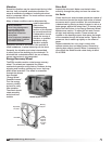
Summer Operation
Outdoor air is preconditioned (temperature and
moisture levels are decreased) by the transfer of
energy from the cooler, drier, exhaust air via the
energy recovery wheel. The preconditioned air is
typically mixed with return air going back to the air
handler for final conditioning.
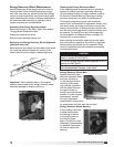
Economizer Operation: Refer to Economizer
Application/Operation section.
Winter Operation
Outdoor air is preconditioned (temperature and
moisture levels are increased) by the transfer of
energy from the warmer, more humid exhaust air via
the energy recovery wheel. The preconditioned air is
typically mixed with return air going back to the air
handler for final conditioning.
Frost Control Operation: Refer to Frost Control
Application/Operation section.
Other Accessories:
Rotation Sensor: Refer to Optional Accessories
section
Dirty Filter Sensor: Refer to Optional Accessories
section
CO
2
Sensor: Refer to Optional Accessories section
VFD on Blowers: VFDs on blowers are often used
as part of a demand control ventilation system. This
type of system takes advantage of varying occupancy
through the use of CO
2
sensors to monitor space CO
2
levels. If CO
2
levels are low in the space, the VFD will
operate the blowers at minimum airflow required by
code. As the space occupancy increases and CO
2
levels increase, the VFD will increase the amount
of fresh outdoor air being brought in to offset the
CO
2
levels in the space (exhaust airflow is increased
proportionally as outdoor airflow increases). As CO
2
levels come back down, the airflow will decrease
back to minimum requirements.
2
3
4
5
7
7
8