


5
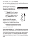
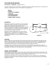
Main
Disconnect
On
Off
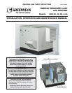
Exhaust
Hood
Control Center
Intake
Hood
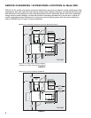
INSTALLATION (continued)
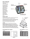
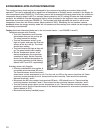
WEATHERHOODS
Supply weatherhood will be factory mounted. The exhaust weatherhood is shipped separately as a kit with its
own instructions.
EXHAUST DAMPERS
Backdraft dampers for exhaust discharge are mounted in the unit. Motorized dampers are shipped loose (inside
ERH) and must be field installed.
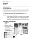
ELECTRICAL CONNECTIONS
The electrical supply must be compatible with that shown on the nameplate: voltage, phase, and amperage
capacity. The electrical supply line must be properly fused and conform to local and national electrical codes.
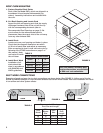
All internal electrical components are pre-wired at the factory. Field electrical connections only need to be made
inside the unit to the main disconnect (See FIGURE 5, Item #1) and the 24 volt control circuit (See FIGURE 5,
Item #7). A door interlocking safety disconnect is provided as standard feature.
Note: Standard factory installed electric post heaters have their own disconnect separate from the unit
disconnect. Thus, electric post heaters require a separate power connection.
IMPORTANT: Use minimum 14 ga. wire for 24 volt control power.
Control wire resistance should not exceed 0.75 ohms (approximately 285 feet total length for
14 ga. wire; 455 feet total length for 12 ga. wire). If wire resistance exceeds 0.75 ohms, an
industrial-style, plug-in relay should be added to the unit control center and wired in place of
the remote switch (between terminal blocks 2 and 3 on the control strip — See FIGURE 5,
Item #7). The relay must be rated for at least 5 amps and have a 24 Vac coil. Failure to
comply with these guidelines may cause motor starters to “chatter” or not pull in which can
cause contactor failures and/or motor failures.
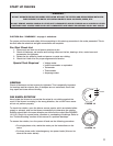
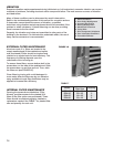
1
2
3
4
6
5
7
8
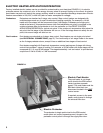
1. Main Disconnect
2. Motor Starter — Exhaust/Scavenger
Air Fan
3. Motor Starter — Outdoor Air Fan
4. Motor Contactor — Energy Wheel
5. Control Power Transformer
(24 VAC Secondary)
6. Energy Wheel Motor Transformer
(230 VAC Secondary)
(for ERH-20 & ERH-45 units with
primary voltage greater than 230 Vac)
7. 24 VAC Terminal strip
8. Fuses for the control circuit, wheel
drive transformer, and blower
motors.
TYPICAL CONTROL CENTER COMPONENTS
FIGURE 5