


12
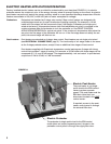
ENERGY RECOVERY WHEEL
CAUTION: See **WARNING** on page 1 and 11
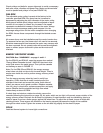
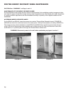
For the ERH-20 and ERH-45, open the access door marked
"Energy Wheel Cassette Access". UNPLUG the wheel drive
motor and remove the metal spacer. Then pull the cassette
out halfway as seen in FIGURE 17.
Note: For the ERH-55 and ERH-90, the energy recovery
wheel does not slide out due to its size and weight. There is
ample room inside the unit to perform energy recovery wheel
servicing.
Turn the energy recovery wheel by hand to verify free
operation. Check that the air seals, located around the
outside of the wheel and across the center (both sides of
wheel), are secure and in good condition. Replace cassette
into unit, plug in wheel drive, replace access door and apply
power. Observe that the standard and high flow wheel
rotates freely at about 60 RPM.
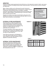
If wheel does not rotate or rotates too slowly, remove the
cassette (following the instruction on page 16). Air seals, which are too tight, will prevent proper rotation of the
energy recovery wheel. Recheck the air seals for tightness. Air seal clearance may be checked by placing a
sheet of paper, to act as a feeler gauge, against the wheel face. To adjust the air seals, loosen all eight seal
retaining screws. These screws are located on the bearing support that spans the length of the cassette
through the wheel center. Tighten the screws so the air seals tug slightly on the sheet of paper.
COILS
Leak test thermal system to insure tight connections.
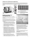
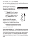
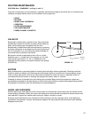
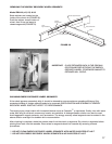
Check pulleys and belts for proper alignment to avoid unnecessary
belt wear, noise, vibration and power loss. Motor and drive shafts
must be parallel and pulleys in line (see FIGURE 16).
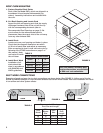
FAN RPM
The adjustable motor pulley is preset at the factory to the
customer specified RPM. Fan speed can be increased or
decreased by adjusting the pitch diameter of the motor pulley.
Multi-groove variable pitch pulleys must be adjusted an equal
number of turns open or closed. Any increase in fan speed
represents a substantial increase in load on the motor. Always
check the motor amperage reading and compare it to the
amperage rating shown on the motor nameplate when changing
fan RPM. Access these components through the labeled access
panels.
All access doors must be installed except the control center door.
To measure the fan rpm, the blower door will need to be removed.
Minimize measurement time because the motor may overamp with
the door removed. Do not operate units with access doors/panels
open or without proper ductwork in place as the motors will
overload.
FIGURE 17
FIGURE 16
WRONG WRONG
WRONG CORRECT