


4
R
o
t
a
t
i
o
n
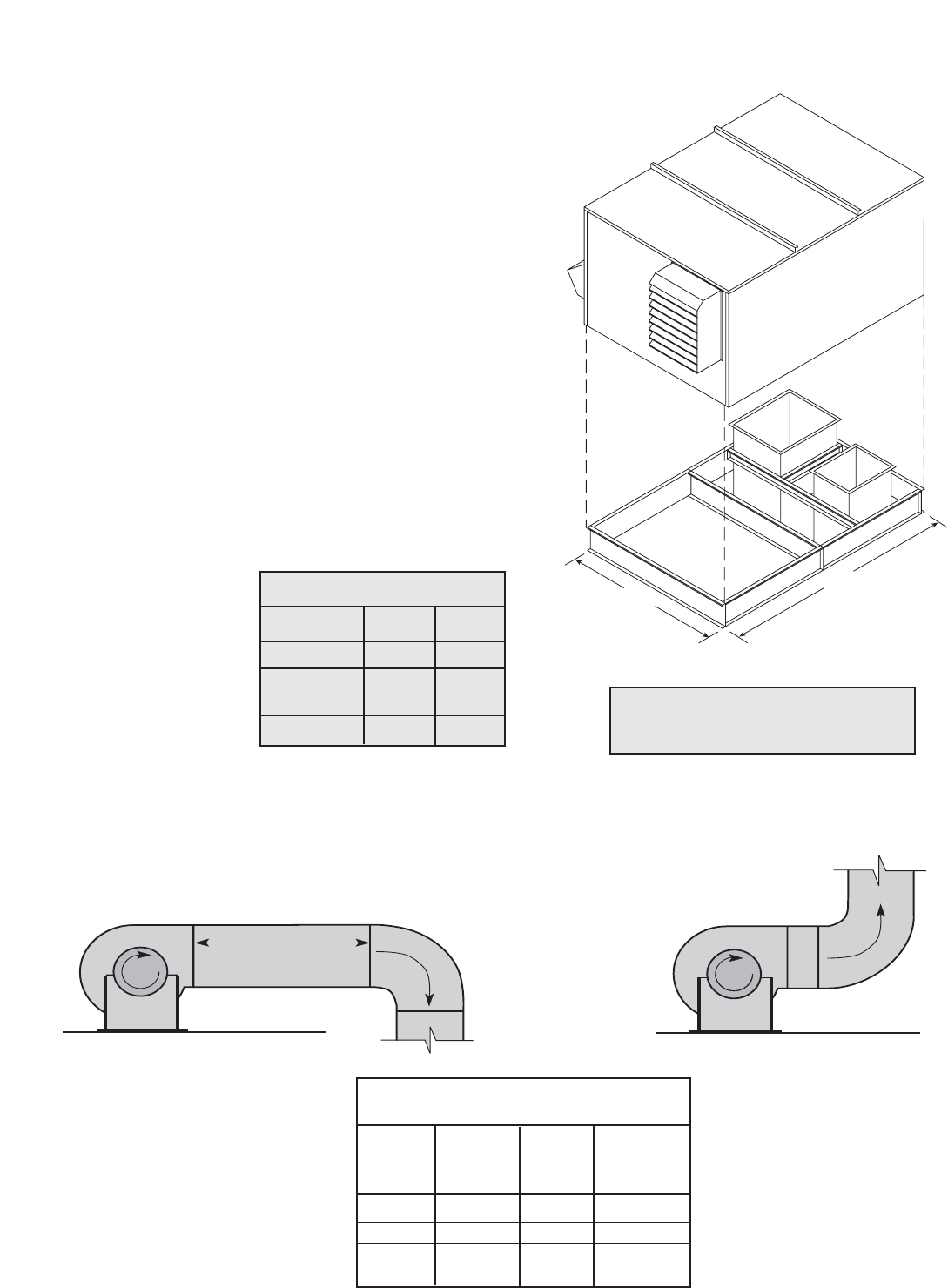
Length of Straight Duct
GOOD
R
o
t
a
t
i
o
n
POOR
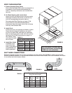
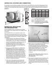
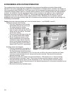
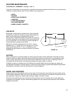
FIGURE 4
DUCT WORK CONNECTIONS
Examples of good and poor fan-to-duct connections are shown below (See FIGURE 4). Airflow out of the fan
should be directed straight or curve the same direction as the fan wheel rotates. Poor duct installation will result
in low airflow and other system effects.
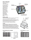
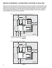
1. Factory Supplied Roof Curbs
Roof curbs are Model GKD, which are shipped in a
knockdown kit and require field assembly (by
others). Assembly instructions are included with
the curb.
2. Cut Roof Opening and Locate Curb
Layout the unit roof opening such that the supply
discharge & exhaust inlet of the unit will line up
with the corresponding ductwork (refer to
Recommended Roof Openings on page 3). Be
sure to allow for the recommended service
clearances. Keep the supply inlet of the unit away
from any other exhaust fans.
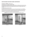
3. Install Curb
Locate curb over roof opening and fasten in place.
Check that the diagonal dimensions are within
±1/8 inch of each other and adjust as necessary.
Shim as required to level. Lower unit onto curb by
following the LIFTING instructions on page 3 of
this manual. Note,
roof curbs fit inside
the unit base.
4. Install Duct Work
Installation of all
ducts should be
done in accordance
with SMACNA and
AMCA guidelines.
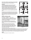
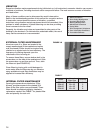
Model L W
ERH-20 73 51
ERH-45 80.75 60.63
ERH-55 94 71.5
ERH-90 106.25 90.75
ROOF CURB MOUNTING
L
W
Curb Outside Dimensions
Dimensions shown are in inches.
FIGURE 3
Roof curb details, including duct
location dimensions, are available
on ERH roof curb submittals.
Recommended Discharge
Duct Size and Length
ERH
ERH
Duct
Straight
Model
Blower
Size
Duct
Size Length
20 10 14 x 14 40
45 12 20 x 20 48
55 15 28 x 28 60
90 18 32 x 32 72
Dimensions shown are in inches.
TABLE 3
TABLE 4