


FAN FUNDAMENTAlS
132
STATIC PRESSURE GUIDELINES
STATIC PRESSURE GUIDELINES
Nonducted 0.05 in. to 0.20 in.
Ducted
0.2 in. to 0.40 in. per 100 feet of
duct (assuming duct air velocity
falls within 1000-1800 feet per
minute)
Fittings
0.08 in. per fitting (elbow, register,
grill, damper, etc.)
Kitchen Hood
Exhaust
0.625 in. to 1.50 in.
Static pressure requirements are significantly affected
by the amount of make-up air supplied to an area.
Insufficient make-up air will increase static pressure
and reduce the amount of air that will be exhausted.
Remember, for each cubic foot of air exhausted, one
cubic foot of air must be supplied.
DETERMINING STATIC PRESSURE (Ps)
The pressures generated by fans in ductwork are
very small. Yet, accurately estimating the static
pressure is critical to proper fan selection.
Fan static pressure is measured in inches of water
gauge. One pound per square inch is equivalent
to 27.7 in. of water gauge. Static pressures in fan
systems are typically less than 2 in. of water gauge,
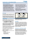
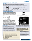
or 0.072 Psi. The drawing below illustrates how
static pressures are measured in ductwork with a
manometer.
A pressure differential between the duct and
the atmosphere will cause the water level in the
manometer legs to rest at different levels. This
difference is the static pressure measured in inches
of water gauge.
In the case of the exhaust fan below, the air is being
drawn upward through the ductwork because the
fan is producing a low pressure region at the top
of the duct. This is the same principle that enables
beverages to be sipped through a straw.
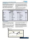
The amount of static pressure that the fan must
overcome depends on the air velocity in the
ductwork, the number of duct turns (and other
resistive elements), and the duct length. For
properly designed systems with sufficient make-up
air, the guidelines in the table below can be used for
estimating static pressure:
Duct
Airflow
Atmospheric
Pressure
Manometer
Water
1 in.
Airflow out of
restaurant
Grill
Damper
Airflow to
exhaust fan
4 ft.
6 ft.
Ductwork
Exhaust Fan
* NOTE: For convenience in using selection charts, round this value up to the nearest 1/8 in., which would be 0.50 Ps.
IMPORTANT!
Introduction to FAN SELECTION
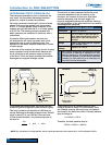
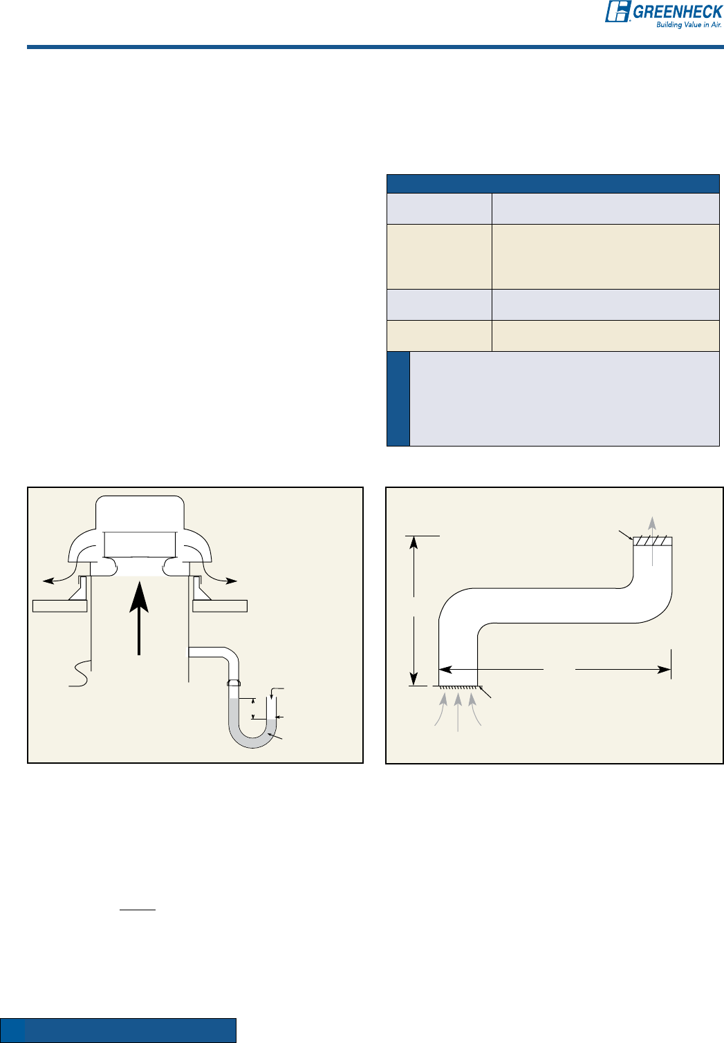
To calculate the system losses, one must know the
ductwork system configuration (see Ductwork figure).
This duct is sized for air velocities of 1400 feet per
minute. Referring to the static pressure chart, that will
result in about 0.3 in. per 100 feet. Since we have
10 feet of total ductwork, our pressure drop due to
the duct is:
There is also a 0.08 in. pressure drop for each
resistive element or fitting. For this example, there
are 5 fittings: one grill, two duct turns, one damper
and louver in the wall of the office. The total pressure
drop for fittings is:
5 x 0.08 in. = 0.4 in.
Therefore, the total pressure drop is:
0.03 in. + 0.40 in. = 0.43 in.*
.3 in.
x 10 ft. = .03 in.
100 ft.