


Installation
3A1450D 5
Installation
Grounding
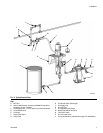
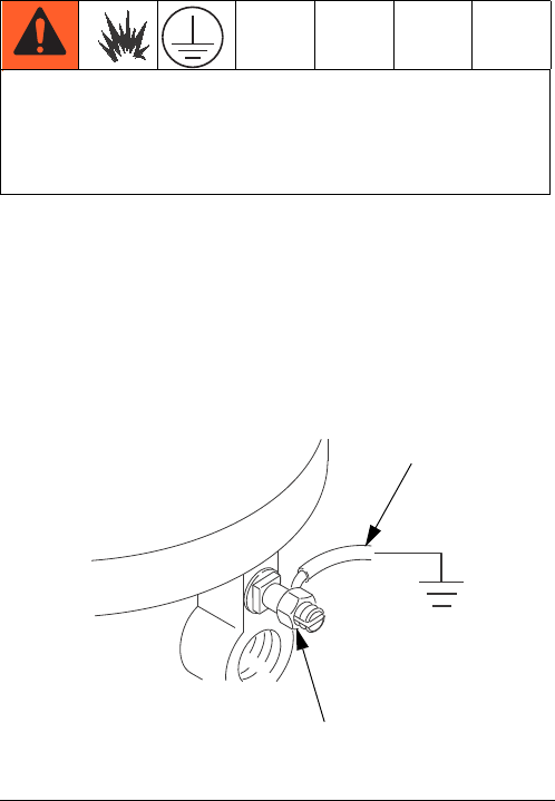
Pump: use a ground wire and clamp (Y). See FIG. 1.
Loosen the grounding lug locknut (W) and washer.
Insert one end of the ground wire into the slot in the lug
and tighten the locknut securely. Connect the ground
clamp to a true earth ground. Order Part No. 237569,
Ground Wire and Clamp.
Air and fluid hoses: use only electrically conductive
hoses with a maximum of 500 ft. (150 m) combined
hose length to ensure grounding continuity. Check the
electrical resistance of hoses. If total resistance to
ground exceeds 25 megohms, replace hose immedi-
ately.
Air compressor: follow manufacturer’s recommenda-
tions.
Surge tank: use a ground wire and clamp.
Dispense valve: ground through a connection to a
properly grounded fluid hose and pump.
Fluid supply container: follow local code.
Object being sprayed: follow local code.
Solvent pails used when flushing: follow local code.
Use only conductive metal pails, placed on a grounded
surface. Do not place the pail on a nonconductive sur-
face, such as paper or cardboard, which interrupts
grounding continuity.
To maintain grounding continuity when flushing or
relieving pressure: hold metal part of the spray gun
firmly to the side of a grounded metal pail, then trigger
the gun.
Stand Mount
Order Part No. 253692 Pump Stand Kit (accessory).
Mount the pump in the pump stand and secure with the
four screws and lockwashers supplied in the kit.
See Mounting Hole Layouts on page 17. Secure the
stand to the floor with M19 (5/8 in.) bolts which engage
at least 152 mm (6 in.) into the concrete floor to prevent
the pump from tipping.
Wall Mount
Order Part No. 255143 Wall Bracket Kit (accessory).
1. Ensure the wall is strong enough to support the
weight of the pump assembly and accessories, fluid,
hoses, and stress caused during pump operation.
2. Ensure that the mounting location has sufficient
clearance for easy operator access.
3. Position the wall bracket at a convenient height,
ensuring that there is sufficient clearance for the
fluid suction line and for servicing the lower.
4. Drill four 7/16 in. (11 mm) holes using the bracket as
a template. Use either of the two mounting hole
groupings in the bracket. See Mounting Hole Lay-
outs, page 17.
5. Bolt the bracket securely to the wall using bolts and
washers designed to hold in the wall’s construction.
6. Attach the pump assembly to the mounting bracket.
7. Connect air and fluid hoses.
The equipment must be grounded. Grounding
reduces the risk of static and electric shock by
providing an escape wire for the electrical current
due to static build up or in the event of a short circuit.
F
IG. 1. Ground Wire
TI0720a
W
Y