


Repair
12 3A1450D
Repair
Disassembly
1. Relieve the pressure, see Pressure Relief Proce-
dure page 8.
2. Disconnect the hoses from the lower and plug the
ends to prevent fluid contamination.
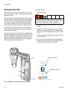
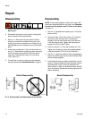
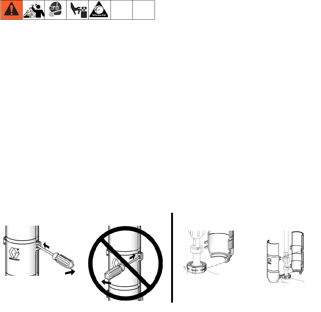
3. See F
IG. 4. Remove the 2-piece shield (109) by
inserting a screwdriver straight into the slot, and
using it as a lever to release the tab. Repeat for all
tabs. Do not use the screwdriver to pry the shields
apart.
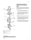
4. Loosen the coupling nut (110) and remove the col-
lars (111). Remove the coupling nut from the piston
rod (R). Unscrew the locknuts (105) from the tie
rods (104). Separate the motor (101) and lower
(102). See F
IG. 5.
5. To repair the air motor or lower, see the separate
manuals listed under Related Manuals on page 2.
Reassembly
NOTE: If the coupling adapter (108) and tie rods (104)
have been disassembled from the motor, see Reassem-
ble the Coupling Adapter and Tie Rods to the Motor
on page 13.
1. See F
IG. 5. Assemble the coupling nut (110) to the
piston rod (R).
2. Orient the lower (102) to the motor (101). Position
the lower on the tie rods (104). Lubricate the
threads of the tie rods. Screw the tie rod locknuts
(105) onto the tie rods. Tighten the locknuts and
torque to 50-55 ft-lb (68-75 N•m).
3. Insert the collars (111) into the coupling nut (110).
Tighten the coupling nut onto the coupling adapter
(108) and torque to 75-80 ft-lb (102-109 N•m).
4. See F
IG. 4. Install the shields (109) by engaging the
bottom lips with the groove in the wet-cup cap. Snap
the two shields together.
5. Flush and test the pump before reinstalling it in the
system. Connect hoses and flush the pump. While it
is pressurized, check for smooth operation and
leaks. Adjust or repair as necessary before reinstall-
ing in the system. Reconnect the pump ground wire
before operating.
FIG. 4. Disassembly and Reassembly of the Shields
ti15759a
Shield Disassembly
ti15770a
ti15757a
ti15758a
Shield Reassembly