


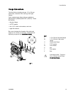
Installation
Fluid Supply L
ine
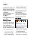
1. Connect a grounded, flexible fluid hose (E) to the
1.5 in (38 mm) ANSI/DIN pump fluid inlet flange
(L). See Ground The System, page 10.
2. If the inlet fluid pressure to the pump is more
than 25% of the outlet working pressure, the
ball check valves will not close fast enough,
resulting in inefficient pump operation. Excessive
inlet fluid pressure also will shorten diaphragm
life. Approximately 3–5 psi (0.02–0.03 MPa,
0.21–0.34 bar) should be adequate for most
materials.
3. For maximum suction lift (wet and dry), see
Technical Data, page 22. For best results, always
install the pump as close as possible to the
material source. Minimize suction requirements
to maximize pump performance.
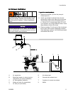
Fluid Outlet L
ine
1. Connect a grounded, flexible fluid hose (H) to the
1.5 in (38 mm) ANSI/DIN pump fluid outlet flange
(M). See Ground The System, page 10.
2. Install a fluid drain valve (F) near the fluid outlet.
3. Install a shutoff valve (G) in the fluid outlet line.
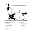
1
2
3A2888A