


Installation
4 3A0427B
Installation
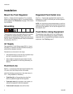
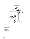
Mount the Fluid Regulator
See F
IG
. 1. Mount the fluid regulator (C) in a location
close to the fluid dispense device. A mounting bracket
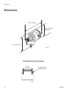
(D) is supplied. See Dimensions on page 14 for mount-
ing information.
Grounding
The equipment must be grounded. Mount the regulator
to a conductive mounting surface (E) which is con-
nected to a true earth ground. Follow local code. Graco
Part No. 222011 Ground Wire and Clamp is available as
an accessory. See F
IG
. 1.
Air Supply
The regulator’s air inlet fittings accept 5/32 in. (4 mm)
OD tubing. Air pressure can be controlled manually or
with electronic pressure controls.
Connections can be made in two ways:
• Use separate high (A) and low (B) air pressure sup-
ply lines, connected as shown in F
IG
. 1.
• Use a single air supply line and connect it to the
high or low pressure air inlet fitting alternately, as
desired.
Fluid Inlet Line
See F
IG
. 1. Connect the fluid inlet line (G) between the
1/4 npt(m) fluid inlet fitting and the fluid supply.
Install the following accessories in the order shown in
F
IG
. 1, using adapters as necessary.
• Fluid filter (H): to filter particles from the fluid
before it passes through the fluid regulator.
• Fluid drain valve (J): required in your system, to
relieve fluid pressure in the fluid regulator.
• Fluid shutoff valve (K): shuts off fluid flow.
Regulated Fluid Outlet Line
See F
IG
. 1. Connect the regulated fluid outlet line (F)
between the 1/8 npt(f) fluid outlet port and the system’s
fluid dispense point.
NOTE: All components located downstream of the fluid
regulator must be rated for the maximum fluid inlet pres-
sure sent to the regulator. Do not use the regulator as a
fluid shutoff valve.
Flush Before Using Equipment
The equipment was tested with a rust inhibiting test
fluid. To avoid contaminating your system, flush the
equipment with a compatible solvent before using the
equipment. See Flushing, page 7.