


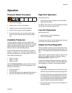
Repair
10 3A0427B
Repair
Disassembly
1. Flush the regulator with a compatible solvent. See
page 7.
2. Relieve pressure. See page 7.
3. Disconnect the air and fluid lines from the regulator.
Remove the regulator for repair.
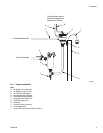
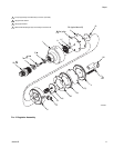
4. Remove the fluid inlet fitting (20). See F
IG
. 2.
5. Remove five screws (17), the air chamber cover (4),
air diaphragm (15), spacer (3), and gasket (29).
6. Unscrew the ratio piston (14). Remove the spring
(13) and air chamber housing (2).
7. Insert a standard screwdriver into the fluid inlet of
the regulator and hold the regulator needle (6)
steady. Unscrew the air chamber piston (10).
8. Remove the fluid diaphragms (9a, 9b), o-ring (11),
and fluid chamber piston (8). Push the needle (6)
out of the fluid chamber housing (1) inlet port.
9. Using a 5/16 allen wrench, unscrew the seat
retainer (7) and seat (5) from the fluid chamber
housing (1).
10. Clean all parts and inspect for damage.
Reassembly
NOTE: Rebuild Kit 24E504 is available. See page 12 to
order. Kit parts are marked with an asterisk, for example
9a*. For the best results use all parts in the kit.
NOTE: Seat Repair Kit 24F140 is available. See page
12 to order. Kit parts are marked with a symbol, for
example 7◆. For the best results use all parts in the kit.
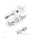
1. Using a 5/16 allen wrench, screw the seat retainer
(7*◆) and seat (5*◆) into the fluid chamber housing
(1).
NOTE: The white ptfe diaphragm (9a*) must always
face the fluid. Install the white ptfe diaphragm first, fol-
lowed by the black nylon/buna-N diaphragm (9b*).
2. Insert the needle (6◆) in the fluid chamber housing
(1). Hold in place with a screwdriver or allen wrench.
Install the fluid chamber piston (8), o-ring (11*), ptfe
diaphragm (9a*), and nylon/buna-N diaphragm
(9b*).
3. Apply thread sealant to the threads of the needle
(6). Screw the air chamber piston (10) onto the nee-
dle. Align the holes in the diaphragms before tight-
ening. Tighten using a screwdriver in the slot of the
needle.
4. Install the air chamber housing (2). Align the holes
in the housing with the holes in the diaphragms (9a,
9b) and fluid chamber housing (1).
5. Install the spring (13). Screw the ratio piston (14)
into the air chamber piston (10).
6. Install the gasket (29*), spacer (3), air diaphragm
(15*), and air chamber cover (4). Align the holes.
Install five screws (17). Torque oppositely and alter-
nately to 25 in-lb (2.8 N•m).
7. Apply pipe sealant and install the fluid inlet fitting
(20).
8. Reinstall the fluid regulator in the system.
Change the Ratio
Ratio Kits 24E501, 24E502, and 24E503 are available
to change the ratio. See page 12 to order. Kit parts are
marked with a symbol, for example 3†. The kits include
a spacer (3†) and piston (14†). The ratio spacer is color
coded to indicate ratio:
• Silver (1:1 Ratio Kit 24E501)
• Green (1:2 Ratio Kit 24E502)
• Black (1:3 Ratio Kit 24E503)
To install the kit, disassemble the regulator (see page
10). Replace the existing spacer (3) and ratio piston (14)
with the desired size, and reassemble. Do not mix spac-
ers and pistons of different sizes.