


18 308441
Service
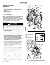
4. Loosen but do not remove the diaphragm shaft
bolts (107), using a 15 mm socket wrench (1 in. on
stainless steel models) on both bolts. NOTE: This
step does not apply to pumps with overmolded
diaphragms.
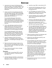
5. Unscrew one bolt from the diaphragm shaft (24)
and remove the o-ring (108), fluid side diaphragm
plate (105), PTFE diaphragm (403, used on PTFE
models only), diaphragm (401), and air side dia-
phragm plate (104). See Fig. 12.
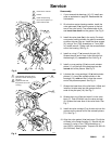
For overmolded diaphragms: Grip both dia-
phragms securely around the outer edge and
rotate counterclockwise. One diaphragm assembly
will come free and the other will remain attached to
the shaft. Remove the freed diaphragm and air
side plate.
6. Pull the other diaphragm assembly and the dia-
phragm shaft (24) out of the center housing (1).
Hold the shaft flats with a 19 mm open–end
wrench, and remove the bolt (107) from the shaft.
Disassemble the remaining diaphragm assembly.
For overmolded diaphragms: Pull the other dia-
phragm assembly and the diaphragm shaft (24)
out of the center housing (1). Hold the shaft flats
with a 19 mm open–end wrench and remove the
diaphragm and air side plate from the shaft.
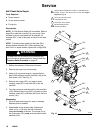
7. Inspect the diaphragm shaft (24) for wear or
scratches. If it is damaged, inspect the bearings
(19) in place. If the bearings are damaged, refer to
page 20.
8. Reach into the center housing (1) with an o-ring
pick and hook the u-cup packings (402), then pull
them out of the housing. This can be done with the
bearings (19) in place.
9. Clean all parts and inspect for wear or damage.
Replace parts as needed.
Reassembly
1. Install the shaft u-cup packings (402*) so the lips
face out of the housing (1). Lubricate the pack-
ings. See Fig. 12.
2. Install the diaphragm assembly on one end of the
shaft (24) as follows. For pumps with overmolded
diaphragms, go directly to step g.
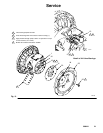
a. Install the o-ring (108*) on the shaft bolt (107).
b. Install the fluid side diaphragm plate (105) on
the bolt so the rounded side faces in, toward
the diaphragm (401).
c. On PTFE models only, install the PTFE dia-
phragm (403*). Make certain the side marked
AIR SIDE faces the center housing (1).
d. Install the diaphragm (401*) on the bolt. Make
certain the side marked AIR SIDE faces the
center housing (1).
e. Install the air side diaphragm plate (104) so
the recessed side faces the diaphragm (401).
f. Apply medium-strength (blue) LoctiteR or
equivalent to the bolt (107) threads. Screw the
bolt (107) into the shaft (24) hand tight.
g. For overmolded diaphragms: Assemble the air
side plate (104) onto the diaphragm (403). The
wide, radiused side of the plate must face the
diaphragm. Apply medium–strength (blue)
Loctite or equivalent to the threads of the
diaphragm assembly. Screw the assembly into
the shaft (24) hand tight.
3. Grease the length and ends of the diaphragm shaft
(24), and slide it through the housing (1).
4. Assemble the other diaphragm assembly to the
shaft as explained in step 2.
5. Hold one shaft bolt (107) with a wrench and torque
the other bolt to 20–25 ft-lb (27–34 NSm) at 100
rpm maximum. NOTE: This step does not apply to
pumps with overmolded diaphragms.
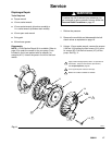
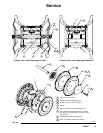
6. Align the fluid covers (101) and the center housing
(1) so the arrows (A) on the covers face the same
direction as the air valve (B). Apply medium-
strength (blue) LoctiteR or equivalent to the
threads of screws (106) and (112), and secure the
covers with the screws handtight. Install the
longer screws (112) in the bottom holes of the
covers. See Fig. 11. Using a 13 mm socket
wrench, torque the screws oppositely and evenly
to 190–220 in-lb (22–25 NSm). See Torque Se-
quence, page 28.
7. Reassemble the ball check valves and manifolds
as explained on page 16.