Motor Control Board
16 3A0246C
Installation
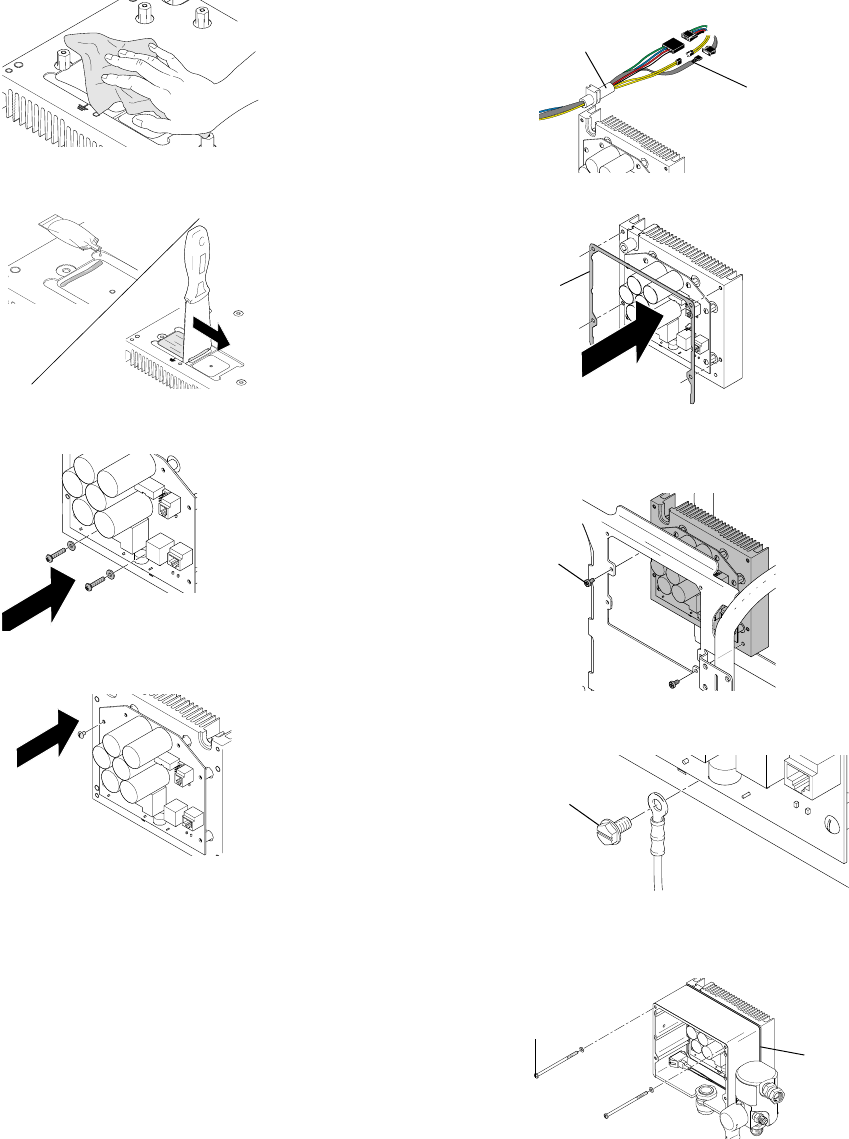
120V Models:
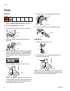
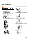
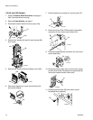
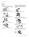
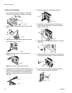
1. Use acetone or equivalent cleaner to thoroughly
remove thermal paste from pockets on heat sink.
2. Apply new thermal paste into both pockets of heat
sink.
3. Replace two inner screws and washers to control
board and torque to 17 in-lb.
4. Replace six outer screws to control board and
torque to 11 in-lb.
NOTE: SW1 position setting does not matter.
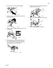
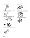
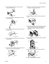
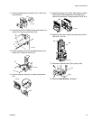
5. Connect motor control board lead connectors (F) to
leads from motor. Insert grommet in heat sink baffle.
Use zip tie or electrical tape (Z) to hold grommet
together on grommet end on the motor side of the
heat sink.
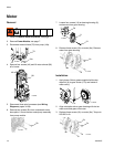
6. Assemble gasket (94) to heat sink assembly.
7. Assemble two screws (83) to hold motor control
board/ heat sink assembly to power module frame.
Torque to 35-45 in-lb.
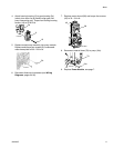
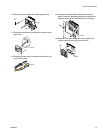
8. Assemble ground screw (58) to heat sink. Torque to
30-34 in-lb.
9. Assemble control box enclosure (3) to power mod-
ule and tighten two screws (61). Torque to 30-35
in-lb.
ti14695a
ti14693a
ti15926a
ti14697a
ti15852a
F
Z
94
ti15911a
ti15845a
83
ti15846a
58
ti15912a
3
61


