


Repair
12 308777L
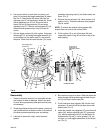
7. Before installing the lock wires (28) in the adjusting
nuts (27), use the special gauge, 171818, to adjust
the transfer valve (M) so there is 0.125 inches (3.68
mm) clearance between the poppets (37) and the
piston (5) when the toggle assemblies are in the
down position.
8. Snap the toggle assemblies (K) to the up position.
Reinstall the cylinder (32) and cap nut (31). Reas-
semble the air motor to the displacement pump.
9. Before remounting the pump, connect an air hose
and run the pump slowly, at about 40 psi (0.28 MPa,
2.8 bar) to ensure that it operates smoothly.
10. Reconnect the ground wire before regular operation
of the pump.
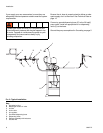
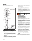
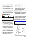
Throat Packing Service
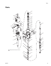
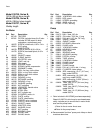
See FIG. 6 on page 12 and the Parts drawing and list
(page 13 and 14) for further information.
1. Clamp the pump in a vise and unscrew the riser
tube (80) from the air motor base (56). Pull the riser
tube away from the air motor until the cotter pin (60)
which secures the displacement pump connecting
rod to the air motor piston rod (52) is visible. (F
IG. 6)
2. Remove the cotter pin (60) and unscrew the pump
connecting rod (79) fro the air motor piston rod (52).
Remove the cylinder (32) from the air motor base
(56) as described in the Disassembly section on
page 10).
3. Remove the louvered air exhaust plate (36) and
unscrew the throat packing nut (45), using a span-
ner wrench or a 0.22 inch (5.6 mm) diameter rod.
(F
IG. 6)
4. Remove the packing nut (45), male and female
glands (47 and 48), v-packings (49), washer (44),
bearing (46), retainer (24), wiper (22), o-ring (23),
u-cup (25), and washer (26) from the base.
5. Clean the throat packing area in the base and the
packing nut. Clean and inspect all parts, and
replace as necessary.
6. Lubricate the packings, piston rod, and piston flange
with a light, water-resistant grease.
7. Install the washer (26) into the base. Assemble the
packing (25) and the wiper (22) into the retainer
(24). Install the o-ring (23) onto the retainer, and
insert the retainer assembly into the base.
NOTE: Make sure the packing (25) lips face down, and
make sure the wiper (22) lips face up.
8. Insert the bearing (46) and the washer (44) into the
base. Assemble the female gland (48), v-packings
(49), and the male gland (47) into the packing nut
(45).
9. Reinstall the spacer and packing in the base and
packing nut (45). Screw the packing nut into the
base, and tighten it securely. Carefully slide the pis-
ton rod (52) down through the throat packing, and
lower the piston into the base. Reinstall the plate
(36) and cylinder (32). Reassemble the air motor to
the displacement pump.
10. Torque the outlet adapter (42) to 45 to 55 ft-lbs (61
to 75 N.m).
The piston in the air motor, located behind the air motor
plates, moved when air is supplied to the motor. Moving
parts can pinch or amputate your fingers or other body
parts. Therefore, never operate the pump with the air
motor plates removed.
NOTICE
When reinstalling cotter pin (60), always spread and
flatten the pin (both the head and prongs) around the
rod to within 1 inch (25 mm) total diameter. See Detail
A of F
IG. 6.
FIG. 6
45
36
80
56
32
SEE DETAIL A
52
60
79
1 in.
(25 mm)
DETAIL A