


Repair
10 308777L
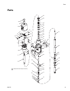
Reassembly
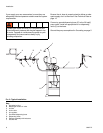
1. Hold the intake housing (67) upright in a vise. One
at a time, place the female gland (74), four leather
v-packings (66) with the lips of the packings facing
up, and the male gland (65) on the intake housing.
Place the gasket (62), seat (68), and ball (59) on the
housing (67).
2. If the pins (77) were removed from the piston valve
housing (64), replace them. Screw the piston vale
onto the intake valve housing.
3. Place a gasket (62), seat (68), and ball (59) on the
priming tube (72). Holding the piston valve housing
(67) with a wrench, screw the priming tube into it,
using a 1/4” diameter rod through the tube for lever-
age.
4. One at a time, place the female gland (76), four
leather v-packings (73) with lips of packings facing
up, a male gland (75), and a bearing (69) in the
packing housing (70). Screw the housing firmly into
the riser tube (80).
5. Guide the piston assembly into the riser tube (80).
Screw the riser tube into the motor base, making
sure the gasket (63) is in place. Install the cotter pin
(60).
6. Torque the riser tube to 50 to 70 ft-lbs (68 to 95
N.m).
7. Screw the priming piston (71) onto the priming tube
(72). Screw the intake cylinder (78) firmly onto the
riser tube.
8. Reconnect the ground wire if it was disconnect dur-
ing repair.
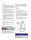
Air Motor and Throat Service
Before You Start
Before sure to have all necessary parts on hand. Air
Motor Repair Kit 207385 included repair parts for the
motor. Pump Repair Kit 239734 includes repair parts for
the pump and the air motor throat area. Use all parts in
the kits for best results.
Two accessory tools should be used: Padded Pliers,
207579, used to grip the trip rod without damaging its
surface; Gauge, 171818, is used to ensure the proper
clearance between the poppets and seat of the transfer
valve.
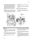
Disassembly
1. Flush the pump.
2. Relieve the pressure, see page 7.
3. Disconnect the air hose from the motor. If neces-
sary, disconnect the motor from the pump. Clamp
the air motor base in a vise.
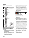
4. Manually push up on the piston rod to move the pis-
ton assembly to the top of its stroke. Unscrew the
cylinder cap nut (31) from the cylinder (32). Pull up
on the cap nut. Grip the trip rod (1) with padded pli-
ers, 207579, and screw the cap nut off the trip rod.
(F
IG. 4)
5. Remove the eight screws (7) holding the cylinder
(32) to the base (56). Carefully pull the cylinder
straight up off the piston. (F
IG. 4)
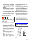
FIG. 4
NOTICE
To avoid damaging the cylinder wall. Always lift the
cylinder straight up off the piston. Never tilt the cylin-
der as it is being removed.
32
7
56
36
1
Hold trip rod with
padded pliers
207579, to prevent
damage to rod
31