Installation
308391J 7
Hydraulic Components
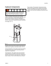
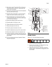
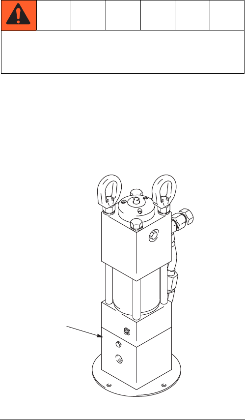
Drain Line: Remove the plug (24) from the pump
adapter, and install a 1/8 inch diameter weep tube, end-
ing in a waste container. Monitor the weepage of
hydraulic fluid. If it seems excessive or increases sud-
denly, the reciprocator or pump throat seals may need to
be changed. (F
IG. 3)
Hydraulic Fluid Control: The hydraulic fluid control pro-
vides pressure regulator, and pump isolation. (F
IG. 2)
Pressure Regulation: The hydraulic fluid control reduces
the hydraulic oil pressure to the operating pressure
required for the application.
Flow Regulation: The hydraulic fluid control limits the
maximum amount of oil flow to the motor to keep the
hydraulic motor within the cycle rate limit. This prevents
pump runaway. The limit on the Power-Star is 66 cpm.
Pump Isolation: The hydraulic fluid control has ball
valves on the supply and return sides of the manifold.
The ball valves isolate the hydraulic fluid control and
pump for servicing without stopping the hydraulic power
supply.
Always turn off the hydraulic supply side valve (K)
first to avoid possible serious injury or component
damage. See the Typical Installation on page 6.
FIG. 3
24


