


8 308768
Installation
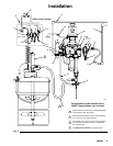
Installing the Pump Module
The pump module consists of the pump mounted on
the pump bracket, the air controls, back pressure
regulator, hoses, and plumbing.
NOTE: Refer to Fig. 2 on page 9, and to the Dimen-
sion drawing on page 22 and the Mounting Hole Lay-
out on page 23.
1. Ensure that the wall is strong enough to support
the weight of the pump and accessories, fluid,
hoses, and stress caused during pump operation.
2. Position the bracket mounting plate (37) on the
wall so the edge with the hook is facing up. Mount
the plate so the top edge is 4 to 5 ft (1.2 to 1.5 m)
above the floor. Check that the plate is level. Mark
two holes on the wall, using the plate as a tem-
plate. Drill two holes and attach the plate with 1/2
in. bolts and washers.
3. Using two people, hang the pump module on the
bracket mounting plate (37). Have one person hold
the module in place while the other checks that the
pump bracket (22) is level. Mark four holes on the
wall, using the pump bracket as a template. Re-
move the pump module.
4. Drill four holes in the wall.
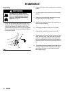
WARNING
The pump bracket (22) must be bolted to the wall
with four bolts. Do not simply hang the pump
bracket on the bracket mounting plate (37).
5. Lift the pump module back into position, hang it on
the bracket mounting plate (37), and bolt the pump
bracket (22) to the wall. Use 1/2 in. bolts and
washers to mount the pump module to the wall.
Use bolts that are long enough to keep the pump
bracket (22) from vibrating during operation.
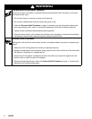
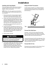
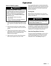
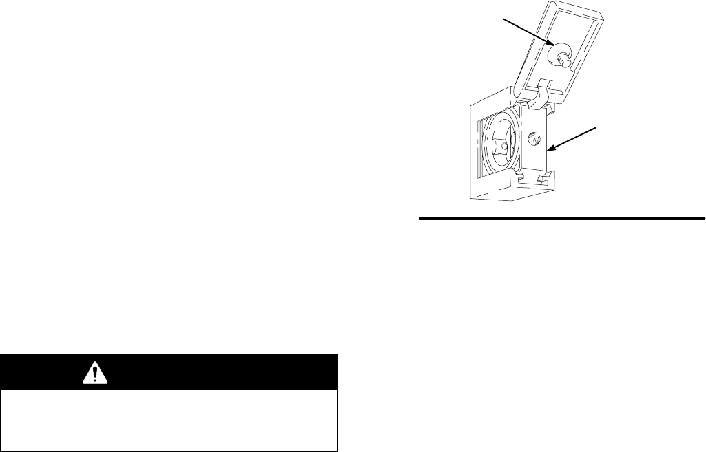
Using the Quick Connectors
To open a quick connector (11c), loosen the captive
screw (S) and open the connector. Slide the desired
component into the connector, close, and tighten the
screw. See Fig. 1.
06278
Fig. 1
S
11c
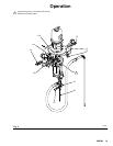
Connect the Fluid Lines
Connect a 1 to 3 ft (0.3–0.9 m) hose (E) to the ball
valve (15) at the outlet of the fluid filter (5), to isolate
the pump module from the main fluid line. Connect the
other end of the hose to the main fluid line (F).
Connect the fluid return line (G) to the ball valve (14) at
the inlet of the back pressure regulator (12). The return
hose (21) connects the back pressure regulator to the
3-way recirculation valve (19).
Connect the Air Line
Connect the main air supply line (A) to the tee (11k) of
the air filter/regulator/lubricator assembly (11).